Changing the value of the Schade resistor will change the amount of feedback, of course, which affects not only the "sensitivity" of the amp (i.e., how large an input signal you need to get rated output) but the stability of the amplifier as well. If you're otherwise happy with 300k then I would focus on making the amplifier stable with that value if you can. In this case, it's really easy.
While you might not see a lot of compensation applied with non-global feedback, it sometimes is necessary if the gain around those stages is large enough. So give the lead compensation capacitor a try and see how that works for you.
While you might not see a lot of compensation applied with non-global feedback, it sometimes is necessary if the gain around those stages is large enough. So give the lead compensation capacitor a try and see how that works for you.
Last edited:
I've had some Russian 6BM8s lurking in my collection for years - maybe this thread will inspire me to break them out and do something with them... I also have an ancient Monarch receiver that I believe uses SE 6BM8s as outputs.
Which mean the Russians make them and EH labels them... Mine might be Sovtek.
Edit - actually, all the the 6F3P examples I've seen on E-pay are Svetlana (original) manufacture.
Edit - actually, all the the 6F3P examples I've seen on E-pay are Svetlana (original) manufacture.
Last edited:
As a reply to Ray's post above, I'm working on a 2-pentode partial feedback SE amp using the 6AH6 and 6L6GC. I had to use a series RC compensation network across the inner feedback resistor for stability as well. No surprises, as it's a feedback network working against an output transformer that likely will have a resonance around 100kHz or so.

Smelly mascot - got a few of those in my neighborhood, though they are the ratty-looking Cali variety instead of the larger and fluffier East Coast types... Nice amp, too. I have Klipsch speakers in my living room - wonder how loud a noise the little amp would make with them.
For another teensy amp, check out this thread. The amp is especially small due to the use of a custom SMPS to eliminate the power transformer.
"Mighty Mite" Single Ended Amplifier
"Mighty Mite" Single Ended Amplifier
Out of curiosity I dug out my 6BM8s and bread-boarded the amp.
I used an Edcor GXSE 10-8-5K transformer with a 4 Ohm resistor in series with a 6 ohm pot for a load and measured power out vs load impedance by varying the 6 ohm pot. I set the amplitude into the load at the beginning of clipping and used 4% THD as my set-point using Audiotester 3d to measure distortion.
RL=4 R Rp = 2500R Pmax = 1.09W
RL=5 R Rp = 3125R Pmax = 2.048W
RL=6 R Rp = 3750R Pmax = 2.16W
RL=7 R Rp = 4375R Pmax = 2.52W
RL=8 R Rp = 5000R Pmax = 2.65W
RL=9 R Rp = 5625R Pmax = 2.56W
RL=10R Rp = 6250R Pmax = 2.3W
Based on these measurements I believe the 5K transformer is indeed a good choice for this amp.
Very interesting! Thank you for your post! Nice way to test for power vs primary impedance.
What 6BM8’s were included in your tests? I’m especially curious if the Russian made ones behave the same way.
What 6BM8’s were included in your tests? I’m especially curious if the Russian made ones behave the same way.
Based on these measurements I believe the 5K transformer is indeed a good choice for this amp.
Thanks for sharing this 🙂
.....Based on these measurements....
At what voltage and current?
Ok, here is data for four Svetlana tubes along with four from various sources.
The same trend shows. The 6BM8 with 40% feedback to the screen has it's impedance lowered to the point that a 5K OPT is better suited than a 7K opt (which is recommended for Pentode mode) for the operating point of the amp as posted by the OP.
The same trend shows. The 6BM8 with 40% feedback to the screen has it's impedance lowered to the point that a 5K OPT is better suited than a 7K opt (which is recommended for Pentode mode) for the operating point of the amp as posted by the OP.
Attachments

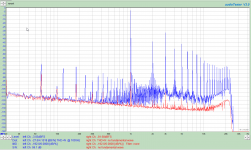
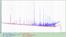
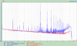
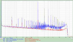
Another observation. There is a distinct difference in the distortion profile and S/N ratio depending on whether the input Triode or output Pentode or both are cathode bypassed.
1 is Pentode bypassed, triode not
2 is Pentode not bypassed, Triode bypassed
3 is both bypassed.
4 no bypass for either
PRR, the voltage is 225V, tube currents are listed in mA in my previous table.
1 is Pentode bypassed, triode not
2 is Pentode not bypassed, Triode bypassed
3 is both bypassed.
4 no bypass for either
PRR, the voltage is 225V, tube currents are listed in mA in my previous table.
Attachments
Last edited:

So would you recommend trying a bypass cap on the triode as well or possibly a LED/diode type cathode method? I would assume either of these would give the input section more drive.
I do plan to experiment with these myself, but would be doing it by ear. You seems to have a better way of testing this stuff than I do lol.
I do plan to experiment with these myself, but would be doing it by ear. You seems to have a better way of testing this stuff than I do lol.
Your bias point for the triode is 1.3V, so you could try two rectifiers in series (1.4V, slightly more bias voltage) or an IR LED (1.1V, slightly less bias voltage).
I will try to test both in the next day or so.
I like to take measurements and try to correlate them to what I hear.
The diodes will act similar to a bypassed cathode resistor in that they will result in slightly higher gain, with slightly higher distortion since there is no or little cathode feedback as there is in an un-bypassed cathode resistor.
If you compare the graphs you will see that #2 (and to some extent #4) without bypass on either cathode has the lowest IM distortion and greatest signal to noise ratio. It also results in the lowest gain of the amp, and requires slightly more drive.
Another thing to note is the distribution of harmonics. In some configurations the odd harmonics are greater than the preceding even harmonic. I find this to be harsh when it is great enough. I believe that monotonically decreasing harmonics sound better.
Whether or not this is important can only be discerned by listening tests.
Last edited:
- Home
- Amplifiers
- Tubes / Valves
- 6BM8 "tiny tube amp" build + Video Series