I plant to try a cree schottky diode + a smaller resistor in series to get to the 1.3V My other amp has a 1.6V LED + 160ohm resistor to "split" it between a bypassed and unbypassed which sounds really nice.
Stephe,
I built similar one last year. I am sure this is a good sounding amplifier. I too did lot of tweaking by ear and and also with scope. Just try these values for a change. Triode Anode load resistor with 220k, cathode resistor 2.2k+100ohm. ,with 2.2k bypassed with 100 mfd. Scahde feedback in mine was 560k. As you very rightly said, it changes the tone. Increasing the resistor value will boost the bass at the cost of reduced highs. If necessary one may add a feedback from secondary of OPT via 3.3k to the point between 2.2k and 100ohm in triode cathode. It depends upon OPT. I prefer to leave it unconnected. Glad that i found one more believer of scahde feedback. I am yet to visit your YouTube channel, but i am going to subscribe right now
I built similar one last year. I am sure this is a good sounding amplifier. I too did lot of tweaking by ear and and also with scope. Just try these values for a change. Triode Anode load resistor with 220k, cathode resistor 2.2k+100ohm. ,with 2.2k bypassed with 100 mfd. Scahde feedback in mine was 560k. As you very rightly said, it changes the tone. Increasing the resistor value will boost the bass at the cost of reduced highs. If necessary one may add a feedback from secondary of OPT via 3.3k to the point between 2.2k and 100ohm in triode cathode. It depends upon OPT. I prefer to leave it unconnected. Glad that i found one more believer of scahde feedback. I am yet to visit your YouTube channel, but i am going to subscribe right now
Last edited:
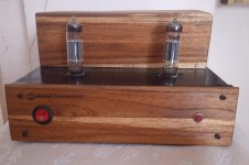
That is a VERY nice looking amp!! 🙂
What I like about Schade feedback, especially for DIY projects: it's not as dependent on the OT, doesn't seem as prone to instability/oscillating, and is a easy to play with tonal tuning tool. And I think what you meant was going from say a 560K to a 300K increases the bass and tames the brightness/high end. At least that's been my experience.
On your amp, what is the plate and cathode voltage on the Triode? It's been a minute but I think I did initially try the 220K/2.2K combo and the plate voltage on the triode, with my trafco, was like 80V, which seemed too low. But I never listened to it there.
This amp was given to my friend couple of weeks back. From my memory IIRC, the anode voltage was around100, with B+ of 230. ( There's a 33k drop resistor in series from B+. Then cathode measure 1.4. I tried experimenting with and without bypass cap on triode while scope monitoring. I did notice that capacitor doubles the RMS voltage. That's a significant boost in volume. You may try both and choose what suits best in your speaker system.
I tried several diodes resulting in the following bias voltage.
1K resistor reference - 1.30V
FR207 x 2 - 1.10V
1N4934 x 2 - 1.05V
IR LED - 1.08V
1N914B x 2 - 1.27V
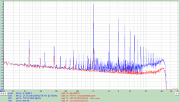
One thing to note about the FR207, 1n4934, and IR LED is that the bias current is only around 1.3mA and as such the (1A and 2A) diodes are biased in the soft knee of the curve.
The 1N914B with two diodes in series has a higher voltage drop due to it's lower max current of 100mA and the operating point being further up the curve in the more linear region where dynamic resistance is lower. If you are trying to use diodes for biasing, this provides a better operation point.
the two attached images are both using the 1n914B x 2 biasing with the first
having the Pentode cathode is bypassed and the second the Pentode cathode is unbypassed.
1K resistor reference - 1.30V
FR207 x 2 - 1.10V
1N4934 x 2 - 1.05V
IR LED - 1.08V
1N914B x 2 - 1.27V
One thing to note about the FR207, 1n4934, and IR LED is that the bias current is only around 1.3mA and as such the (1A and 2A) diodes are biased in the soft knee of the curve.
The 1N914B with two diodes in series has a higher voltage drop due to it's lower max current of 100mA and the operating point being further up the curve in the more linear region where dynamic resistance is lower. If you are trying to use diodes for biasing, this provides a better operation point.
the two attached images are both using the 1n914B x 2 biasing with the first
having the Pentode cathode is bypassed and the second the Pentode cathode is unbypassed.
Attachments
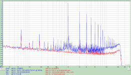
Diode or bypassing the driver cathode resistor increases gain by decreasing feedback (since unbypassed resistor raises the output impedance of the stage). Likewise unbypassed cathode resistor on the output reduces gain and output, especially at low frequencies, as the inductive reactance of the transformer goes down. Simple circuit, but many things interact.
There is a lot going on between the two graphs. Look closely at the IM distortion in addition to the harmonic distribution.
The Gimp,
You are correct.
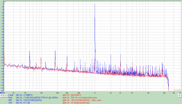
The 60Hz fundamental, and the 60 Hz harmonics at 120, 180Hz, etc., all inter-modulate with the 1 kHz fundamental test tone.
And they inter-modulate with the harmonics of the 1kHz test tone, at 2kHz, 3kHz, etc.
But all of those IM products are at least 85 dB below the 1kHz fundamental.
I would not loose any sleep over hum/hum harmonic intermods of a low power amplifier like that.
On the other hand, the harmonic distortion is perhaps a little higher than some might want it to be.
Or is it possible that the signal generator has some harmonic distortion?
A function generator is easy to get, a low distortion generator is harder to find.
A quick check of the generator is to see how much distortion it creates by itself.
Builders and owners of that amplifier, go ahead and enjoy listening!
Just my opinions.
You are correct.
The 60Hz fundamental, and the 60 Hz harmonics at 120, 180Hz, etc., all inter-modulate with the 1 kHz fundamental test tone.
And they inter-modulate with the harmonics of the 1kHz test tone, at 2kHz, 3kHz, etc.
But all of those IM products are at least 85 dB below the 1kHz fundamental.
I would not loose any sleep over hum/hum harmonic intermods of a low power amplifier like that.
On the other hand, the harmonic distortion is perhaps a little higher than some might want it to be.
Or is it possible that the signal generator has some harmonic distortion?
A function generator is easy to get, a low distortion generator is harder to find.
A quick check of the generator is to see how much distortion it creates by itself.
Builders and owners of that amplifier, go ahead and enjoy listening!
Just my opinions.
Last edited:
The generator is an old Heathkit IM-17 with about 0.025%THD. Second is down 90dB, 3rd is down 83dB, and the rest are down 100dB or more.
I consider it sufficient for power amp testing, but not preamp testing.
I agree 6A3sUMMER that the amp should be enjoyed by Stephe. She might like trying some combinations of bypassing an non-bypassed to see if she can hear a difference.
I probably couldn't.
I consider it sufficient for power amp testing, but not preamp testing.
I agree 6A3sUMMER that the amp should be enjoyed by Stephe. She might like trying some combinations of bypassing an non-bypassed to see if she can hear a difference.
I probably couldn't.
Attachments
Last edited:
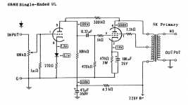
I finally got around to doing some final mod testing. I ended up changing the coupling caps from a "fast" Solen to a Mundorf Alum/Oil EVO of the same value, which was an improvement. I then swapped out the unbypassed 1Kohm cathode resistor on the triode, for a combo of a Cree C3D02060A, 2A 600V, Silicon Carbide Schottky Diode in series with 270ohm resistor, which gave the amp a huge increase in power from the standard line input off my DAC. The final mod I tried, that was a failure, was a 10pf cap across the Schade feedback resistor. While it cleaned up the square wave pattern on the scope, the amp sounded dull and lifeless and it wasn't a subtle change, so I took that back out.
Here is the final video and schematic.
6BM8 DIY Tube Amplifier - Final mods with scope/listening tests - YouTube
Here is the final video and schematic.
6BM8 DIY Tube Amplifier - Final mods with scope/listening tests - YouTube
Attachments
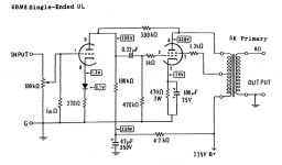
These are very lovely schematics. Do you make them with pen and ink, or is there a magical modern substitute?
All good fortune,
Chris
All good fortune,
Chris
These are very lovely schematics. Do you make them with pen and ink, or is there a magical modern substitute?
Photoshop 🙂
Assuming (yeah, I know) that many folks have played with old bootleg versions of Photoshop 4 or maybe even 10 year old versions of Elements, is your technique something that would lend itself to a YouTube video?
You get a very beautiful look that seems totally missing from today's computer "enhanced" drawings. Part of what you get comes from your technique, but an equal part comes from a classical eye for style, which really couldn't be taught in a video. If the technique part could be translated to video, it might be a big hit. Just spitballin'.
Thanks as always,
Chris
Assuming (yeah, I know) that many folks have played with old bootleg versions of Photoshop 4 or maybe even 10 year old versions of Elements, is your technique something that would lend itself to a YouTube video?
That's a great idea for a future video! Thanks.
...
Both examples you mentioned in your last posting are exactly the ones that grossly exceed the pentode's plate dissipation rating at 10 and 9.2 watts, respectively. I'd really not recommend that in SE and other class A designs.
...
You arrived at your 10 and 9.2 Watts by multiplying the values for B+ and for current consumption that are mentioned in the two examples TS linked to in post #32.
But plate dissipation is the voltage between cathode and anode times the anode current. So not included are (voltage wise) the voltage drop in the cathode resistor and in the output transformer, and (current wise) the screengrid current and the current of the preamplifier stage (and possibly in a bleeder).
Because of this, and looking in the Philips datasheet for the ECL82 and the PCL82, I doubt if the maximum plate dissipation of the beam power section (7 Watt) is exceeded in the two examples.
From a practical point of view
I would think that a beginner is better off soldering a socket of the EL84 than the socket of the ECL82 (6BM8). I know that from experience.
I would think that a beginner is better off soldering a socket of the EL84 than the socket of the ECL82 (6BM8). I know that from experience.
In the beginning of my rediscovery of this hobby, still being blissfully ignorant about wiring capacitances, I built this amplifier with ECL82's. It worked fine (no hum/noise/oscillations).
Back than I have built many other amplifiers with all kinds of power tubes in this 'naive/breadboarding' style (EL3, EL5, EL34, PL36, EL86, EL360, EL504, E130L and KT88). The only time I experienced trouble was when using E130L's (in triode mode) but these tubes have a very high mutual conductance of 27.5 mA/V and are prone to oscillate.
The purpose of this post is not to entice beginners to 'build to last' in this naïve and ofcourse unsafe style (but it does allow for easy modifications!). I'm using metal chassis for my builds myself for some time now. The purpose of this post is to downplay the worries a bit about possible oscillations/noise when a beginner uses the ECL82.
Attachments

Hi Steph,
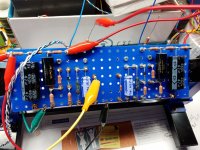
I've been following this thread for a while and decided as we headed into another lockdown here in NZ that this would be a great first project for my daughter to try, she's thirteen and loves music so great project to spend time together and she will learn a few things along the way.
We started by transferring the schematic to a turret board designer called DIY Layout Creator and worked from there.
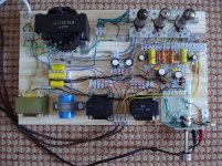
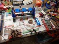
Progress as of last night, Amp board complete with components mounted on one side and tubes on the other. We needed to test the old stock power transformer would supply enough current to both the heaters and the amplifier itself. Photo of all parts breadboarded up and tested with iPod feeding amp and a single speaker connected to left channel. Sounds great considering speaker is not in a cabinet, though very little bass lol.
Only change we made was to use an EZ81 (6AC4) rectifier as we needed a little more voltage drop to reach the desired B+.
Maddy and I will post a few more pics as we progress, today she will be getting a crash course in AutoCAD to layout the components for the chassis plate. its great as a template or sometimes I just send the file to a local waterjet firm and let them cut them out 😀
Thanks for posting this, its a great project for a beginner. 🙂
I've been following this thread for a while and decided as we headed into another lockdown here in NZ that this would be a great first project for my daughter to try, she's thirteen and loves music so great project to spend time together and she will learn a few things along the way.
We started by transferring the schematic to a turret board designer called DIY Layout Creator and worked from there.
Progress as of last night, Amp board complete with components mounted on one side and tubes on the other. We needed to test the old stock power transformer would supply enough current to both the heaters and the amplifier itself. Photo of all parts breadboarded up and tested with iPod feeding amp and a single speaker connected to left channel. Sounds great considering speaker is not in a cabinet, though very little bass lol.
Only change we made was to use an EZ81 (6AC4) rectifier as we needed a little more voltage drop to reach the desired B+.
Maddy and I will post a few more pics as we progress, today she will be getting a crash course in AutoCAD to layout the components for the chassis plate. its great as a template or sometimes I just send the file to a local waterjet firm and let them cut them out 😀
Thanks for posting this, its a great project for a beginner. 🙂
Attachments

- Home
- Amplifiers
- Tubes / Valves
- 6BM8 "tiny tube amp" build + Video Series