The seller would say anything to sell that soviet garbage.
Hello, I am with you on the OTL thing heard them a few times, wondering if i am hearing what you are hearing in that what you don't like?
Thanks
Last edited:
Built a few but abandoned the valve in the end because they had self resonance issues which was very noticeable with my 100db/w speakers. Produced a high pitched wine which would come and go at random. Others have reported similar experiences in headphone amps using these valves.
Shoog
Shoog, you are one of my most favorite diyers just wanted to thank you for what you do 🙂
will 6080's have this problem with hi pitched wine?
I don't know in any given situation. I remember that my first DC7 amp only exhibited it when the valves had done about a years service. This amp was considerably simpler than the later versions of the DC7 which were direct coupled - and they were the ones which consistently whined all the time. I think it was an instability induced by the cathode CCS's and the large grid of the 6080. No matter what I tried I could never tame it and so gave up on the project altogether. However I would say that many people using 6080's with insensitive speakers might never hear the whine at all.
Shoog
Shoog
one more question sir if you will, instead of CCS would blumline garter circuit balance current enough to use torriod power trans for output?
Lawrence
Lawrence
I have used this on a ECL82 PP headphone amp - and it works excellently. However it really isn't appropriate for use with 6080's since the already large cathode wastage would be criminal .
Shoog
Shoog
Hey All, I've been thinking that I might use a 6P15P pentode as a voltage amp. That way I can get all the voltage swing I need in one stage. And the pentode predilection for even order harmonics might help to cancel the even order harmonics of the 6N13S. I was reading about the "Scrap Box Challenge" in MJ. I was really impressed with the 6528 he used until I found only one on eBay at $79.95. Parts collection has been on the order of scrap box as well. I have two Magnavox OPT's that I hope to use. They're 4k but I have them. I can always custom order a pair later if necessary.
You'll get no sound and probably some fire.
I'd you fix the first two stages and get rid of the self destructing current regulators on the output stage, then you'll be left with an amp that makes a few tenths of a watt.
I'd you fix the first two stages and get rid of the self destructing current regulators on the output stage, then you'll be left with an amp that makes a few tenths of a watt.
In normal case when output transformer is directly connected to anode,
the voltage swing at the anode can be (in theory) from zero to 2 x +Ub.
Now with CCS at the anode, the voltage can swing only from +Ub to zero.
Half of the voltage swing is lost.
The use of a CCS is sensible at voltage amplifying stages, but not in typical PP or SE output stages.
There is also CCS at the cathode. Which one is now determining the anode current, upper or lower ?
Only one can determine the current, the other is not working as a CCS.
Typical cathode resistor will do fine.
Member
Joined 2009
Paid Member
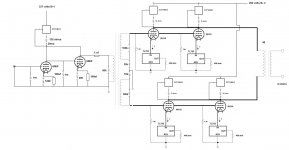
Schematic
You are going to heroic efforts on this one - having built a 6AS7 single ended amp as my first and only stereo amplifier I can say from experience that it's a lot of fun to play with a big tube like this. But I'd not recommend it for an all-out effort, this tube is an awkward beast. It drinks heater current, being a tube that likes low impedance loads with lots of current. And the high grid bias means lots of heat spent in the cathode resistor. Anyhow, my suggestion is to keep it simple. The latest circuit is way too complicated in my humble opinion.
Perhaps you could look at a self-splitting push-pull design. You get to use a CCS and no need for a phase splitting inter-stage transformer.
The self-splitting concept can be see in this example: Poddwatt: Class-A Stereo Push-Pull EL84 (6BQ5) Vacuum Tube Amplifier
For the 6AS7 you want lowish B+ because this tube runs better at higher current and you don't want too much B+ to over-heat the anode. That doesn't leave so much room for the driver stage. But a choke loaded driver stage will give you the most swing at limited B+. The trick is to be very careful at the build stage, you need to keep these plate chokes away from the power transformer or you'll get plenty of hummmmmm, so build a mock up and work out how the transformers and chokes need to be placed with respect to each other.
Last edited:
Member
Joined 2009
Paid Member
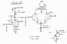
Self-Splitting 6AS7 PP
This is a rough sketch of what I had in mind. Un-proven and probably missing something somewhere! - at least I didn't check that the gain is enough from triode-wired pentode (likely requires 3V rms input), you may need to operate it as a pentode to get more gain, or place two resistors in series from plate to ground and tap the mid-point to the pentode screen - you get partial feedback and you can set the gain of the input stage where you like it and according to your 'ears'. OR you can try a higher gain triode, there are plenty of options with mu around 70.
The more complex option, if you don't want to deal with a plate choke on the driver is to us a voltage doubled power supply. Set up the output stage with a B+ around 180V (high current) and voltage double that for the front end at around 300V after filtering (low current).
fyi: Hammond 156C - good Plate choke load??
Attachments
Last edited:
A self spliter circuit relies on the MU to do the heavy lifting of the circuit and that means a high MU works best. The 6AS7 has a MU of 2 which makes it just about the worst candidate for a self spliter.
My recommendation is something like my DC7 Mk1 design which a few people built and listened to and said it sounded good. The recipe is a 5687 driving the interstage in parafeed arrangement. This does the splitting. Load the 5687 with a CCS to get maximum gain. The outputs work well at 100V anode to Cathode with 100mA of current. Put a CCS in each cathode and then cross couple the 6AS7 cathodes to each other with back to back 1000uF caps for quasi-differential output. Replace the 5687 for an ECC99 for a better result.
Shoog
There are a few other proven PP designs out there for this tube.
Member
Joined 2009
Paid Member
I don't see the mu as an issue at all in this case. Yes, the shared cathode voltage will experience large swings, just as the driven grid of the first tube must but it's no worse than driving the grid (and the cathode has mu of 3 whilst grid is only 2).
I've no direct experience of trying it, but I don't believe your assertion. Can you explain further ?
I've no direct experience of trying it, but I don't believe your assertion. Can you explain further ?
Self-splitting means that some half of the output power ( of normal PP) is lost.
Output impedance and THD are higher too, so where are the pros ?
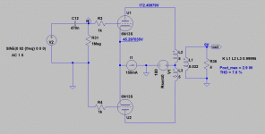
This would be a very bad design. Self split with 180 V +Ub will produce less than 3 W with high distortion.
Normal PP with optimum +Ub (375 V) will give more than 12 W with half the THD. See post #7 and #19 (schematic and test results).
Output impedance and THD are higher too, so where are the pros ?
Set up the output stage with a B+ around 180V (high current)
This would be a very bad design. Self split with 180 V +Ub will produce less than 3 W with high distortion.
Normal PP with optimum +Ub (375 V) will give more than 12 W with half the THD. See post #7 and #19 (schematic and test results).
Attachments
Last edited:
Member
Joined 2009
Paid Member
Oh I see, I forgot that self-splitting like this only works in Class A. Depending on speakers, 2.5W is perfectly fine (some 2A3 amps don't put much more). For Class AB in tubes I have no idea what I'm talking about 😀
Like Shoog I found 6080 are Too micro-phonic.
I have Horn loaded X two 18 inch & horn loaded compression drivers over 100DB
I tried many different types of 6080's 6AS7's worst were Carbon Plate 6080's best to forget these very micro-phonic tubes with sensitive speakers
I have Horn loaded X two 18 inch & horn loaded compression drivers over 100DB
I tried many different types of 6080's 6AS7's worst were Carbon Plate 6080's best to forget these very micro-phonic tubes with sensitive speakers
Like Shoog I found 6080 are Too micro-phonic.
How is this observed in practise ?
I have used 6N13S triodes and not seen this behaviour at all.
The amplifier I presented earlier has been built some 12 pcs.
None of the DIYers have reported anything about microphonics.
I have heard a sufficient number of people report this at this stage for people to take it seriously. The common factor - high sensitivity headphones or very high sensitivity speakers. If you are using speakers of less than 96db/w its unlikely you are going to hear what we have heard - I suppose thats lucky for you.
As to why not to use a 6AS7 in a self splitter. When I proposed this as one of my first design ideas I was told it was a bad idea. The reason would be the same reason why an anti-triode is best implemented using stiff pentodes or mosfets - because the extra gain allows it to better follow the cathode signal without introducing its own distortion.
Shoog
I have heard a sufficient number of people report this at this stage for people to take it seriously.
So we don't know how the microphonics is located to be at 6AS7G and not in any other part of the amplifier.
To me it would be more obvious that the voltage amplifying stages are causing the problem. There the signal level is typically some 40...46 dB lower.
The signal level at full power at the grid of 6AS7G (PP) is 250 Vpp and gain some 1.5.
To me it is hard to understand how this combination can be microphonics.
Just now I asked at the Finnish hifi-forum for those who build my version of 6AS7G PP to comment about the microphonics. Let's see what I get.
- Home
- Amplifiers
- Tubes / Valves
- 6AS7GA as push pull output?