The information is in table 4.5-Output Transformer Comparison, in Morgan Jones, Building Valve Amplifiers, 2nd edition (page 342).
A quality power toroidal only makes a good output transformer under two conditions: low impedance valves (because of high shunt capacitance of bifilar winding) and no DC in the cores requiring AC coupled cathodes and individual exactly matched current sinks for each cathode. Additionally, high power is totally unrealistic. For very efficient speakers, however, an excellent result can be achieved; I think many have tried this by now.
A quality power toroidal only makes a good output transformer under two conditions: low impedance valves (because of high shunt capacitance of bifilar winding) and no DC in the cores requiring AC coupled cathodes and individual exactly matched current sinks for each cathode. Additionally, high power is totally unrealistic. For very efficient speakers, however, an excellent result can be achieved; I think many have tried this by now.
piano3 is correct on the DC balance. I have built 5 amps with Triad VPT transformers all using CCS cathode bias.
I've had good performance from a tetrode connected 6P1P amp using a VPT12-2170 which reflects about 12000R:8R with good results.
I've also built using 6L6 tetrode, KT88 triode and KT120 triode.
The latter amp is flat within +-0.5db from 6Hz-50kHz sine at 2W output.
Full power is 33W@1kHz sine, 18W 30Hz sine using Triad VPT18-13800 transformers.
It passes a 10kHz square wave so well I thought I had the scope attached to the input.
It's the best sounding amp I've ever heard.
Last edited:
Interestingly, several (including Morgan Jones) have commented on the excellent 10kHz performance of quality mains toroids.
Kodabmx, it's interesting that you've had good results with beam tetrodes; how did you make absolutely sure that the anode current was balanced?
Kodabmx, it's interesting that you've had good results with beam tetrodes; how did you make absolutely sure that the anode current was balanced?
I use a Cathode CCS scheme from Broskie with a few modifications.
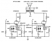
Here's a triode connected KT88/6550 (I'm using KT120 now) but the same applies for tetrode.
The 10,000uf cap charges up through the diode until it reaches the cathode voltage at which point the diodes are no longer biased and effectively fall out of the circuit.
If however there is a loud passage the diode will conduct and the cap can supply the extra current. Think class A with bursts of class AB.
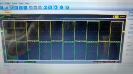
I also included a trace.
Top is DDS, bottom is amp output. 10kHz.
Here's a triode connected KT88/6550 (I'm using KT120 now) but the same applies for tetrode.
The 10,000uf cap charges up through the diode until it reaches the cathode voltage at which point the diodes are no longer biased and effectively fall out of the circuit.
If however there is a loud passage the diode will conduct and the cap can supply the extra current. Think class A with bursts of class AB.
I also included a trace.
Top is DDS, bottom is amp output. 10kHz.
Attachments
Last edited:
Wow! That is pretty amazing. Yes, the triode scheme is as I would expect but how do you control the screen current in tetrode connection so that it doesn't unbalance the anode current?
Yes, amazing square response indeed.
Is this the toroid you have used: VPT18-13800 Triad Magnetics | Mouser Europe
Can you take a scope plot with 30 Hz sine wave at 18W you mentioned?
Here in Europe this is quite meaningless option since it is too expensive compared to real OPT's.
Is this the toroid you have used: VPT18-13800 Triad Magnetics | Mouser Europe
Can you take a scope plot with 30 Hz sine wave at 18W you mentioned?
Here in Europe this is quite meaningless option since it is too expensive compared to real OPT's.
Last edited:
Wow! That is pretty amazing. Yes, the triode scheme is as I would expect but how do you control the screen current in tetrode connection so that it doesn't unbalance the anode current?
I didn't. The B+ is 290V G2 tied to B+ and it's biased as pure class A with LM317.
Yes, amazing square response indeed.
Is this the toroid you have used: VPT18-13800 Triad Magnetics | Mouser Europe
Can you take a scope plot with 30 Hz sine wave at 18W you mentioned?
Here in Europe this is quite meaningless option since it is too expensive compared to real OPT's.
Thank you. I should mention the actual amp uses a global feedback loop.
Yes, that's the transformer. They cost me 88 CAD from digikey with free shipping. Meanwhile a suitable proper OPT is twice that. In reality the 160VA model would have been better and less money but they don't stock it.
I'll scope it at my next convenience as I'm using the bench to rebuild a power supply (SMPS overheated and failed, replacing it with a linear supply).
The heater supply in the following amp schematics is absent but I use 12V SMPS which also powers the 400V SMPS.
Cheers
Attachments


Last edited:
I just realised I was talking about a 6P1P amp but I posted the 6P3S. Yes I know 300V@56ma exceeds the PaMax but they work fine, they cost like $1 and I like running them hot.
It's the same schematic but the current set resistor is 22R, and the transformer is a VPT12-2270 25VA. Good for about 10W.
It's the same schematic but the current set resistor is 22R, and the transformer is a VPT12-2270 25VA. Good for about 10W.
A bit different but some might find this of interest
Projekty lampowe - triodowy wzmacniacz mocy - 20 lamp uses 6N13S, even has details for winding the transformer...
It seems to be in Polish google translate will give a readable English version
regards
Projekty lampowe - triodowy wzmacniacz mocy - 20 lamp uses 6N13S, even has details for winding the transformer...
It seems to be in Polish google translate will give a readable English version
regards
<snip>It is hard to see how a mains x-former would work well with only a few Henries since it would be like putting a short circuit across the mains.
Say "few" = 2. Then 2H, times 50Hz, times Pi twice, is 628 Ohms reactive. At 240V, 0.38 Amps reactive current. A lot for a small part, but far from "short".
OTOH, as an audio output we may try to hold 240V AC as low as 50Hz, but we don't have any reasonable-size (affordable) tubes which come close to 0.38 Amps RMS (540mA peak).
My experience is that a small (10VA) 120V winding will pull near 50mA at 50Hz. This suggests more like 9.5H. The same core wound for 240V would be 30H-40H.
As has been said: inductance will change a LOT with voltage, frequency, and stray DC.
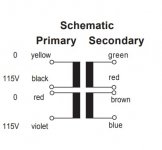
I've attached a screen capture of the Audio Express article from an earlier post in this thread. Seems pretty good to me? My intention is to use the dual primary 115/230 to 12 volts which will give me a reflected impedance of about 2.7k for an 8 ohm load.
If you look at the transformer schematics it is not wired the way I would have expected. So there is something to what Shoog mentioned about wiring them 'correctly.' Digikey wants $32.60 each for these transformers. I spoke with a guy at Talema today he said he would measure the primary inductance at 20hz
and email what the Henries are.
My friend Arlyn at Heyboer could build me a 2.5k to 8 ohm 20 watt OPT using M3 core material for about a hundred bucks each. The point is not to use an inexpensive transformer. The experiment is to see if an inexpensive transformer can be made to sound good. Besides, the toroid under the chassis will require a single hole to mount it. If they don't work out that hole will be covered by an E-I core from Heyboer above the chassis. Nothing to lose, $140 to save.
Attachments


Last edited:
@piano3
The following data is from Triad magnetics.
"Inductance depends on the drive level and the permeability of the core (which can vary significantly). Having said that, I have reviewed some history data from various lots and here are the results.
1. VPT230-110 = 213 to 439H @ 230V, 50Hz (primaries in series). 304H average from 15 samples.
2. VPT230-220 = 192 to 444H @ 230V, 50Hz (primaries in series). 283H average from 15 samples.
3. VPT230-430 = 93 to 214 @ 230V, 50Hz (primaries in series). 128H average from 15 samples."
The same applies for the rest of the VPT series, as the primary is the same.
Still waiting to hear from Talema. piano3 what kind of reflected load is that going to give you?
I have a question. If you look at Artsalo's design he uses individual 47k plate resistors for the 6SN7's in the second stage. A resistor that large would drop a lot of B+ across it, more than I have to spare without using a separate power supply. If I were to use an IXCP10M45S the resistor necessary to make a constant current source for the pair of tubes at 14ma would be 200 ohms. I know that the 47k resistor along with the plate resistance forms a voltage divider which sets the gain of the stage. The 200 ohm series resistor would drop 2.8 volts along with whatever is necessary to turn on the device. After all that, would the device act as a plate resistor and would it give me the necessary gain I need?
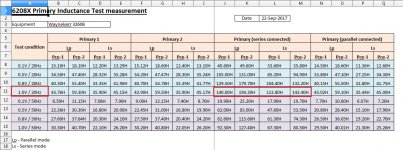
This is what Talema sent me. From my small experience designing a pair of interstage transformers, (with help) The primary inductance at 20 hz is what you have to shoot for. So I asked them to test it at 20hz. This seems a lot better than 2 Henries. If I understand this correctly I'm interested in series connected series mode?
Anyone know what they mean by series mode?
Anyone know what they mean by series mode?
Attachments
Last edited:
Too bad they didn't test it at a higher voltage, say 100V.
Without any DC current through the primary will that really matter?
Below 50hz these transformers will likely suffer significant core saturation with elevated voltages. Piltron audio OT are generally about 4x as big as power transformers of similar power rating - this is because the core has been enlarged to sustain the large magnetic fluxes they are subjected to in the 10-50hz range.
So I think it will make quite a significant difference whether these transformers are tested at 1v or 100v since at one volt the core will be carrying a lot less flux than at 100v.
This is the underlying logic of my 4x rule of VA rating to Wattage output - but its still probably not enough.
Shoog
So I think it will make quite a significant difference whether these transformers are tested at 1v or 100v since at one volt the core will be carrying a lot less flux than at 100v.
This is the underlying logic of my 4x rule of VA rating to Wattage output - but its still probably not enough.
Shoog
Thanks Shoog, You always give me information I can use in a way I can understand it. Heyboer has built me many really good output transformers. As I've found in the past its always easier to start with a transformer designed for the circuit rather than adapt a transformer. I'm going to be breaking new ground (for me) on this amp so it seems wiser to avoid a compromised transformer. Thanks again.
- Home
- Amplifiers
- Tubes / Valves
- 6AS7GA as push pull output?