teifbassuebertr, I think this is the one.
The table does not list the load impedance realized by any of these CCS circuits, and most of them will not be good. A proper ring of two (not J) and K would be the best of the lot, with type K being in common use here in the tube forum. Search on CCS here.
The table does not list the load impedance realized by any of these CCS circuits, and most of them will not be good. A proper ring of two (not J) and K would be the best of the lot, with type K being in common use here in the tube forum. Search on CCS here.
YES!
I can not find a reference to K or J type CCS. Can anyone explain?
you find it??
Attachments

I think balanced operation ensures linearity. So #B or #C, whichever that works.
I'm struggling to find out what will make an amp with good bass performance. From practice, amps with #C have good bass, so may be there is something in it. I'm not there yet.
Hi Jay!
this CCS it is simple, and good!
you can test it, and advance to me!
thanks
Attachments
Hi Jay!
this CCS it is simple, and good!
you can test it, and advance to me!
In your new ccs (where led is not connected between base and Vee), led effect is minimal. I don't know how you connect the led, but proper connection (led symbol pointing upward) performs better.
The performance of the new ccs is in general slightly better than the previous led-based ccs. Very slightly that I don't think it matters (listening test should be conducted but I don't think the difference will be audible). The most noticeable effect, tho very slightly, is that the new ccs has lower noise in all frequency. I think it is understandable from looking at the number of the led used and its position related to Vee.
hi all!
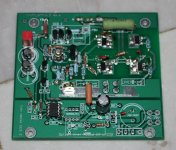
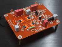
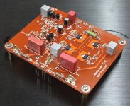
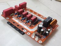
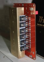
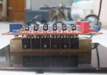
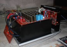
take quite some time, and I finally completed amplifier 637, with such modifications and certain combinations, to invite you to view images!
Thank you
take quite some time, and I finally completed amplifier 637, with such modifications and certain combinations, to invite you to view images!
Thank you
Attachments
-
 CS2.jpg545.9 KB · Views: 631
 -
 CS-637.1.jpg644.6 KB · Views: 609
 -
 Supply-637.4.jpg588.5 KB · Views: 506
 -
 Supply-637.9.jpg712.1 KB · Views: 486
 -
 Supply-637.10.jpg651.4 KB · Views: 451
 -
 Supply-637.11.jpg664 KB · Views: 410
 -
 Supply-637.7.jpg783.8 KB · Views: 475
 -
 Supply-637.5.jpg872.1 KB · Views: 515
 -
 Supply-637.3.jpg620.5 KB · Views: 437
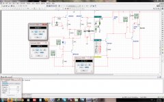
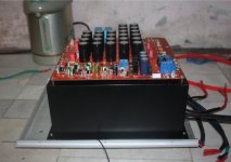
That is really neat, but my original comments still apply. This circuit is not like the OPA637. The special thing about the OPA637 is the input stage, everything else is conventional. This amp should not be named after the opamp; that is just misleading.
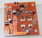
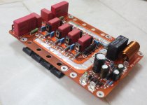
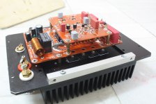
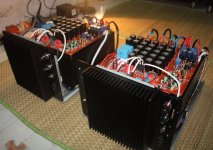
Hey, which ferrite beads do you use for your FETs? Are they on both pins except the gate? Anyway it's an extremely nice build and looks incredible. Did you get the chassis from siliconray perhaps?
From your latest schematics it looks like this amp is a tweaked Goldmund clone rather than an OPA637.
From your latest schematics it looks like this amp is a tweaked Goldmund clone rather than an OPA637.
Hey, which ferrite beads do you use for your FETs? Are they on both pins except the gate? Anyway it's an extremely nice build and looks incredible. Did you get the chassis from siliconray perhaps?
From your latest schematics it looks like this amp is a tweaked Goldmund clone rather than an OPA637.
yes, I see Gm and Anthony.E.Holton amli, all is one design.
All from topo symmetrical
Maybe I copy Too
I buy chaissic from China.
Thanks
Last edited:
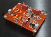
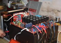
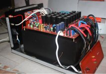
Nice work. Are the toroidal transformers in the power supply epoxy potted?
power transformer is because Vietnamese people, wrap,
I use two power transformers 0 - 58.5 V x 1A for one chanel.
Thanks
I use two power transformers 0 - 58.5 V x 1A for one chanel.
1A ?? Are you shure? You have 12 pcs of expensive power mosfets for each channel.
1A ?? Are you shure? You have 12 pcs of expensive power mosfets for each channel.
I would guessed 1KVA
- Status
- Not open for further replies.
- Home
- Amplifiers
- Solid State
- 637 Amplifiers