Hi Jim and Ralph,
I'm still waiting for the amps (TPA3116) and the rotary encoder, but will start assembling the SG4 so long. I can get a 150W 24V SMPS for ~ $42, or build a linear PSU (160VA toroid with 24V & 12V sec, rectifiers, capacitance multipliers and reservoir caps) for $45-$50. The SMPS is the quickest and easiest, but I still have reservations about switched mode PSUs so close to a SUT and phono amp. What sort of specifications must I keep my eyes open for as regards the SMPS RFI is concerned?
Ralph, is 50VA a good trade off between the 60VA you are using and the original 30VA you mentioned for the output xfmr? The toroidal supplier will wind the step-up xfrs to spec for me, but their standard sizes are 30VA, 50VA & 80VA etc. I have 3 of the Papst 3-phase motors (2 x TD-124s and a spare obtained some years ago with a gutted Micro-Seiki DD100 TT) - I will be building 2 of the 3-phase units to drive the Thorens tables and another 3 to drive Premotec based TTs (one for me and two for friends.)
Could you also please explain exactly how the 3 xfrs connect to the Papst motor. A post in the "Driving a VPI Optimally" thread left me a tad bit confused as to the 3-phase wiring.
Last and definitely not least, a very big thanks to both of you for getting this DIY project out here for us who not too clued up (speaking for myself 😀)
Kevin
Last edited:
Ok after last nights failure, I have regrouped and am ready to have at this again.
I am going to give it another go as I have an extra board and parts.
Could someone verify my earlier question on the IC orientation.
I am going to win this time
I am going to give it another go as I have an extra board and parts.
Could someone verify my earlier question on the IC orientation.
I am going to win this time
Hey Flame
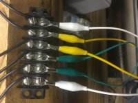
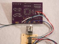
Here is some pictures which may help you out. I built 3 rotary switches 1st one worked 2+3 did not. I may have smoked the chip or there could of been shorting on some of the joints. Who knows without a scope hard to really see the whole picture. The moral of the story for me was use the schematic Pyramid has posted in the thread and use thru hole stuff.
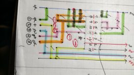
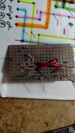
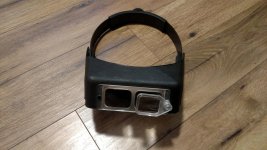
I posted a picture of my version which might save you some set up time. I used the boards which have the rows connected in one direction. Then I used solid 20 gauge wire to bridge the rows and a demel tool with small bit cuts the connected rows. You can scrape it also. The board will be about twice as big but you can see what you are doing and what has been done. I also threw in a picture of a cheap magnifier if you do not have one. Even thru hole stuff when double checking joints is not that large.
I realize the schematic I did was done for myself and not for instruction help. It may give you a idea of what is involved.
Enjoy the ride
Tom
Here is some pictures which may help you out. I built 3 rotary switches 1st one worked 2+3 did not. I may have smoked the chip or there could of been shorting on some of the joints. Who knows without a scope hard to really see the whole picture. The moral of the story for me was use the schematic Pyramid has posted in the thread and use thru hole stuff.
I posted a picture of my version which might save you some set up time. I used the boards which have the rows connected in one direction. Then I used solid 20 gauge wire to bridge the rows and a demel tool with small bit cuts the connected rows. You can scrape it also. The board will be about twice as big but you can see what you are doing and what has been done. I also threw in a picture of a cheap magnifier if you do not have one. Even thru hole stuff when double checking joints is not that large.
I realize the schematic I did was done for myself and not for instruction help. It may give you a idea of what is involved.
Enjoy the ride
Tom
Attachments
flamethrower1,
I don't have the SG4 unit here anymore that I built for my friend to take a look at for you but I looked at the chip that I used and indeed it looks like yours. So I used the line on the one end as orientation towards the capacitors. And the capacitor also have a line on them and the line is the positive end. If you were in no big hurry I'd be more than glad to help you out just mail it to me and I can do a one day turnaround.
TomWH,
I'm also going down the three phase hookup route and so far I have one out of two configurations work for me. Delta and Star and the Delta with my testing setup is working fine so far with amps getting and staying around 120f degrees.
Attachments

Thanks for the info.
I watched a couple of videos on soldering SM parts which were helpful and I will look into a pair of those fancy goggles.
I found a website on locating pin one in case anyone else has the same question
Basics: Finding pin 1 | Evil Mad Scientist Laboratories
I watched a couple of videos on soldering SM parts which were helpful and I will look into a pair of those fancy goggles.
I found a website on locating pin one in case anyone else has the same question
Basics: Finding pin 1 | Evil Mad Scientist Laboratories
flamethrower1,
I don't have the SG4 unit here anymore that I built for my friend to take a look at for you but I looked at the chip that I used and indeed it looks like yours. So I used the line on the one end as orientation towards the capacitors. And the capacitor also have a line on them and the line is the positive end. If you were in no big hurry I'd be more than glad to help you out just mail it to me and I can do a one day turnaround.
TomWH,
I'm also going down the three phase hookup route and so far I have one out of two configurations work for me. Delta and Star and the Delta with my testing setup is working fine so far with amps getting and staying around 120f degrees.
Thanks for your generosity, I just may take you up on that offer, will let you know.
Thanks Greg
So apparently I have the Chinese version of the Texas Instruments IC.
It only has a printed bar across the body at one end for a reference for mounting.
Is this the O end?
Sorry to ask what I am sure is a stupid question, tried to find some info on the web first and everything I found, they referenced a dimple or dot.
Pin 1 of the chip is the lower left corner (pin) of you pic. On the PCB, pin 1 is denoted by the circle in the silk screen.
As Tom indicated, the line on the caps denotes the positive end.

flamethrower
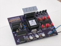
I'm going to solder my second control board up shortly and I laid the parts out.
Thanks, appreciated.
What motor are you going to drive with the three phase set up
Thanks, appreciated.
What motor are you going to drive with the three phase set up
The empire turntable Papst motor.
I just noticed that the board only has 15 holes in it for the 16 pin IC socket
What do you do with the one that is not used?
What do you do with the one that is not used?
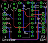
For those that do not want to mess with SMT components, I redid the PCB in thru-hole parts. The board width increased by 0.1". The tantalum caps are 2.5mm lead spacing and the resistors are 1/8W (Mouser PN 299-10KRC).
The OshPark Link is: [url]https://www.oshpark.com/shared_projects/W6QWOCOF[/URL]
The OshPark Link is: [url]https://www.oshpark.com/shared_projects/W6QWOCOF[/URL]
Attachments
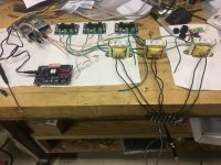
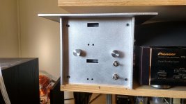
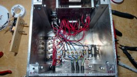
Bill you are making this way to easy!!! Everyone must suffer a little before they have a nice one button control. OK I must admit I just ordered 3 have the parts for one more complete unit. I put a picture of 2 sg4 units in a remote case. I was hurting for space in the front of the rack so I built 2 Sg4 in a high rise like NY city. Now I can put the two different amp/etc units in back to drive the two turntables. One advantage is if I change motors and need another supply just a few wire changes and I am ready to go. I also kept the boards stock just machined opening to see displays and the holes to put a rod thru to change phase and voltage. Like you said how many times are you going to change the phase or running voltage.
Well for the folks coming in late the Sg4 with this rotary switch is a no brainer. Having 3 different frequency generators before the Sg4, I can tell you this is the best by far. Bill is a real asset to this DIY crowd.
Thanks Bill
Tom
Well for the folks coming in late the Sg4 with this rotary switch is a no brainer. Having 3 different frequency generators before the Sg4, I can tell you this is the best by far. Bill is a real asset to this DIY crowd.
Thanks Bill
Tom
Attachments
That's a pretty serious case!
You can get the displays closer to the faceplate opening by stacking several IC sockets on the PCB and inserting the display into the last one to raise it up from the PCB.
You can get the displays closer to the faceplate opening by stacking several IC sockets on the PCB and inserting the display into the last one to raise it up from the PCB.
Attachments
Last edited:
That's a great idea. I also could have turn the voltage reg around the get a little closer, but already built boards and was to lazy to unsoldered etc. Your idea is perfect make the display higher with out all the wires and then make the stand offs.
Thanks for the tip
Tom
Thanks for the tip
Tom
That pic is from my 1st prototype PCB and the resistor was added to make the E²PROM work correctly. It is R22 on your version of the PCB. Likewise, all the other resistors are R18-R21 on the final board.
You should not have any additional components on the bottom of the PCB. If you stuff the board properly, everything will work correctly.
You should not have any additional components on the bottom of the PCB. If you stuff the board properly, everything will work correctly.
Just received an email from Digikey saying that the ribbon cable for remote display is obsolete with a recommended substitute, here is the link
EOL or Obsolete Part
EOL or Obsolete Part
- Home
- Source & Line
- Analogue Source
- 60 WPC Amplifier for DIY Turntable Motor Drive