Hi guys!
Progress is being made but slowly. COVID19 slowed down delivery of some bits and pieces understandably but I am partially working from home so I get to nibble away at this when I have down time. Stay safe everyone!
I have a handful of questions if anyone can give them a look if they have a mo, please?
1. I'm using these Kycon KPJX power connectors (£6.50!!!!!!! 😡) with the 24v / 9.2a PSU and I'm confused by the data sheet. It says:
"Electrical Characteristics
Contact Rating
3 Position: Pin 1 and 2, 48V DC at 7.5A Max.,
Pin 3, 48V DC 1.0A Max.
4 Position: 48V DC 7.5A Max. For All Pins
Insulation Resistance: 50 Megohms Min. at 250V DC
Dielectric Withstanding Voltage: 500V AC For 1 Minute
Contact Resistance: 30 milliohms Max."
Does this mean I can use any single pin for full power draw or do I have to use "all" pins ganged together? I know this sounds a bit naive but the data sheet, to me, is not very clear.
2. (WRT 1.) Will 20AWG be sufficient for power between input, power switch, and amplifier board? I will be using 24AWG for the wireless and DSP boards.
3. What rating of fuse is appropriate for the amp board? PSU will have its own fuse at mains. With all six channels going will it draw 9.2a (max from PSU?
4. I will be putting fuses before the DC-DC isolators with the recommended values from the manufacturer. (0.2a slow blow). Do I need any fuses after these for the DSP/Wifi boards - seems excessive?
5. I'm getting tired of the Up2Stream power up time (no fault of the board, just me being impatient). So, I am going to bypass the power switch for only this board and have it on all the time the unit is plugged in to the PSU. This will make it a nicer use experience for my friend. Can anyone see any issues with this?
Cheers for all the help this far, it's shaping up nicely because of it. I decided to restart the speakers because I wasn't happy with the finish but hopefully I'll have some pictures of them this weekend! 🙂
Attachments
The "for all pins" is meant for the 4 pin version. Think of a separate, solid ground connection, then you can load each of the 4 pins with 7.5A
If you use one pin for ground and one for + you can flow 7.5A or use 2+2 in parallel and you are good up to 15A. Important is which current passes through the single contact. In and out, if you use 2 contacts, means you have the full current at both contact, even as you flow only 7.5A of power.
Any fuse is a resistor. Use as few as possible. Normally one in the AC 230V line should do it.
Which AWG you use is basically a question of what voltage drop you want to allow and how long your wires are. You can calculate this from the Ohm/kilometer (or what unit you prefer) data of the wire.
Such a small amp does not need very much. 16 AWG should be fine for DC power, 18 for speaker. For AC 230V 20AWG is enough.
Leaving electronics on all the time is no problem, if the power draw can be tolerated. Except from Class A and tubes, may be.
Last edited:
3. What rating of fuse is appropriate for the amp board? PSU will have its own fuse at mains. With all six channels going will it draw 9.2a (max from PSU?
The TPA3116/3118 chips have over-temp and over-current shut down protection built in. From the datasheet: "Integrated Self-Protection Circuits Including Overvoltage, Undervoltage, Overtemperature, DCDetect, and Short Circuit With Error Reporting".
I'd personally skip the amp fuse and just make sure you have cooling slots on the sides and/or top of the enclosure so the fan can move some air.
Thanks Ed and Wolf!
I was thinking that about the power supply as well. It also has over temp, over voltage and over current protection and no doubt has a fuse plus the mandatory UK plug fuse!
The PSU is the 4 pin variety, 2 of which are '+' and the other 2 '-'. I can use one pin for full 24v/9a then? I am thinking I can.
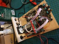
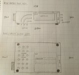
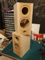
My plan for the forced convection cooling system is this:
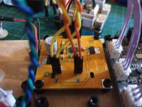
The board in the previous post is actually the wrong way up during development and assembly. It will in fact be the roof of the enclosure/chassis and there will be intake holes on the bottom of the enclosure toward the front. This will force moving air over the warm DC-DC isolators and down the fins of the heatsink then out the back.
I hope I won't need a terrific amount of fan speed to do this and will be putting a 1w trim pot in line with the fan voltage to vary this.
It might even be a good idea to investigate channeling the air flow a la the Behringer iNuke fan hood which I tore off. Second picture attached. Maybe this is overkill, though?
This sketch was done on my lap on my sofa, I hope it is clear! Coupled with the image above I am sure you can get the idea. Any feedback welcome 🙂
I was thinking that about the power supply as well. It also has over temp, over voltage and over current protection and no doubt has a fuse plus the mandatory UK plug fuse!
The PSU is the 4 pin variety, 2 of which are '+' and the other 2 '-'. I can use one pin for full 24v/9a then? I am thinking I can.
My plan for the forced convection cooling system is this:
The board in the previous post is actually the wrong way up during development and assembly. It will in fact be the roof of the enclosure/chassis and there will be intake holes on the bottom of the enclosure toward the front. This will force moving air over the warm DC-DC isolators and down the fins of the heatsink then out the back.
I hope I won't need a terrific amount of fan speed to do this and will be putting a 1w trim pot in line with the fan voltage to vary this.
It might even be a good idea to investigate channeling the air flow a la the Behringer iNuke fan hood which I tore off. Second picture attached. Maybe this is overkill, though?
This sketch was done on my lap on my sofa, I hope it is clear! Coupled with the image above I am sure you can get the idea. Any feedback welcome 🙂
Attachments
I have used 3116 and 7498e for preconditioning of woofers. Even with a lot of constant cone movement, these amps did not even get warm. The SMPS were just as cool.
I think, if we try to be objective, there is no need for special cooling devices, fan´s and stuff. Seems like DIYS over engineering. Be more practical, maybe connect speakers or load resistors and let it work hard for an hour, than use your finger or an IR thermometer.
Some holes in the bottom, a little escape at the top, and all is "tres chic".
Cheers, I take your point and you may be right but here are my reasons.
24v with six 4ohm drivers
Four tpa3116 chips
Undersized heat sink
9mm mdf/ply box
I think I may be going over the top but I can always disable the fan if not needed or turn it way down.
Sounds a bit like I'm patching up a problem that should have been dealt with earlier but its all a learning curve!
Anything someone writes here about a specific problem is remote judgement.
So I can not deliver a 100% perfect answer or solution to something at your table, but maybe I can point you into a direction.
What is "hot" or "cold" with electronics, is very subjective. Your finger starts to hurt between 50 and 60°C, an average chip is perfectly happy while having 125°C inside.
What we don´t know is the thermal resistance between the transistor inside the amp chip and your finger.
A good approach should be to have no touchable part that feel´s more than comfortable warm to the touch.
If you start to wrap your amp into insulation material like wood, you have worse conditions as running the amp on the table, for sure.
You are dealing with Class D. Maybe you never build any A/B amps. While the D-amp does not get much hotter when turned loud (look at data sheet´s. Efficiency gets better with higher output! ), the A/B amp produces more than 60% heat at medium load. So 60w at the speaker may make 90w loss at the heat sink!
If you would start to build an A/B amp with your subjective need for cooling, you probably would use a fan of 50cm diameter for 60 Watt´s of amp power.
Let us have a look at your amp. 4 x3116 and 24v and 6x 4 ohm speaker.
The datasheet shows 80% at 10w. 10 Watt is very loud. Enough for a party in an average flat with neigbour´s calling the police. Make it 6 times 10w.
6x 10x .2 =12 Watt heat to get rid off!
Now, to get an idea about heat sinks, have a look at your average PC cooler. Even the most basic, cheap €8 CPU cooler for low end PC use, can keep a chip happy while it is producing 65w of heat. Now you may realize that the heat sink at your D-amp is not really that small.
To make things even better, the 3116 has reliable over temperature protection build in. So if it really gets to warm, it will shut down. This is, by the way, the point where most fake A/B chip amps fail. There are no fake 3116 on the market till now.
Maybe last, about using wood or plastic for amp cases.
I have been repeatedly bashed for promoting metal cases, as most of these amps are used open, wired up with some shoe sting´s from the garbage bin and used that way for ever... such users don´t want to hear about safety.
In the EU (you are in the lucky situation to leave it soon) there are rules about elektro magnetic emissions. Your D-amp may share frequency´s with many other services. If something goes wrong, your loudspeaker wires can become a very good antenna to emit high frequency.
While ICE amps, Hypex, Pascal etc. are tested and pre-certified for any of such emissions, the Chinese cheapo amps are not.
If you find your amp heating up the output coils at idle and don´t hear anything in the speaker, you can be sure it is oscillating. You can only guess at which frequency.
You have a lot of threads here, where exactly this is a problem.
Especially the air traffic has all kind´s of systems running in a frequency range (200-500kHz) that can be amplified by an ill build D-amp. I don´t want to be in the shoes of someone getting localized transmitting such a frequency near an air port. My (5GHz) W-lan shuts down frequently because of flight radar, by the way.
In the US you will see a prison from the inside even when you play with a laser pointer...
By putting an amp in a metal case you screen it very well, it is the best you can do as a hobbyist. Side effect is a good transmission of heat to the outside, even without any opening.
Just to give some ideas, not criticizing your work.
Cheers Wolf!
No, I completely get you and that really puts thing in to perspective. I appreciate you taking the time to explain in detail. If I had the precision tools for metal work I would but it's a little beyond me at the moment.
You are right, I have not built any other class of amp and perhaps I should to get a better idea, globally. I'd like to try a low wattage class-A at some point to power some compression drivers I have - that will waste some heat watts!
Joy / Disaster
A weird days work...
It started off going great, I installed the fuses for the DC-DC isolators with a little fuse daughter-board and soldered and set up the DAC to output a mono balanced signal and daisy chained to both inputs of the BTL chips. Everything worked a treat!
DISASTER...
Now I had it all fused up I left it on with one speaker driver connected to the main master chip and went to do some shopping with the old ball and chain for a couple of hours.
When I got back the heat sink was unusually hot considering no load and after a few minutes of admiring my handy work I connected a second driver to the master chip (so the master chip was outputting on both channels) and then all of a sudden it started outputting DC in a pulse to one speaker. The speaker that was connected whilst I was out was pulsing, the other not.
The slave chips seem to be OK and function. The master chip returns to functioning after a while of being disconnected but returns to pulsing.
Any thoughts on the cause?
Options...
So, I have a few:
- Order a new board and hope it was the running of the chip with only one driver attached that fried it and not do that again.
- Attempt (again) to get a handful of my TPA3118/3116 stash boards to work together in master/slave modes.
- Try a different TPA3116 5.1 board.
- Tell my friend I don't know what she is talking about and that I never said I would make her a sound system and move to the South Pole.
Last edited:
Did you have something driving the inputs when you had only one channel hooked up to a load? IIRC that's a no-no. On the other hand, if the inputs weren't hooked up I thought it was OK not to have a load connected. Just to be safe, I always practice "safe connections" and have loads on all the channels whenever I power up the amp. Sometimes it's a pain, but I have 6, 50W power resistors so it's just a matter of connecting the wires to the amp.
In any case - I'd be happy to send you my amp which looks identical to yours. All channels are set to 20 dB gain. You'd have to remove the extra heat sink I added (probably just replace it with your stock heat sink). I decided to go another direction and use the 4 channel 3e Audio amp, the DAC and a two channel TPA 3116 amp. So mine is just sitting in a drawer collecting dust. Might as well put it use. Just send me a PM with your address information.
Cheers.
Ed, you continue to be an absolute gentleman!
Very kind, I'll PM you 🙂
Yeah, it's strange, I couldn't find anything in the datasheet about being idle with or without load. Yes, I had the DSP connected with only one speaker on the output. I've learned a lesson (which I should have already by now but I am a big misinformation skeptic, often to my detriment). Luckily I was only using two Faital Pro 3FE25 drivers I had left over from another project and luckily they only cost £10 each here. Their magnets were warm so they must be fried
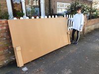
In other news - Today my wife and I made our final non-essential visit out although, I considered it very essential. We don't drive and I was fretting about what I'd do when/if a lock-down comes in here in London or the UK. So, my wife very kindly agreed to help me carry a 34kg 18mm MDF sheet a mile home from B&Q.
I made us little hanger handles and poor Becky had to stop often (she's only 47kg in weight) but she took one for the team! I now have enough board for 2-3 pairs of speakers depending on what I make.
God bless her, she's a teacher and still has to go in to look after the vulnerable kids so well done her!
Stay safe everyone!
Very kind, I'll PM you 🙂
Yeah, it's strange, I couldn't find anything in the datasheet about being idle with or without load. Yes, I had the DSP connected with only one speaker on the output. I've learned a lesson (which I should have already by now but I am a big misinformation skeptic, often to my detriment). Luckily I was only using two Faital Pro 3FE25 drivers I had left over from another project and luckily they only cost £10 each here. Their magnets were warm so they must be fried
In other news - Today my wife and I made our final non-essential visit out although, I considered it very essential. We don't drive and I was fretting about what I'd do when/if a lock-down comes in here in London or the UK. So, my wife very kindly agreed to help me carry a 34kg 18mm MDF sheet a mile home from B&Q.
I made us little hanger handles and poor Becky had to stop often (she's only 47kg in weight) but she took one for the team! I now have enough board for 2-3 pairs of speakers depending on what I make.
God bless her, she's a teacher and still has to go in to look after the vulnerable kids so well done her!
Stay safe everyone!
Attachments
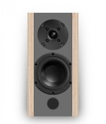
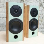
Progress is being made! Almost done with the satellite cabinets, I just need to bevel the front vertical corners, cut some tubes and mount things.
Drivers going in will be:
SB Acoustics SB19ST-C000-4 Tweeter
https://www.falconacoustics.co.uk/downloads/SBA/SB19ST-C000-4.pdf
&
Peerless HDS-P830870 Mid-Woofer
Peerless by Tymphany HDS-P830870 - 4" Woofer
They look to be a good match. The slim baffle (aesthetics first in this build) gives a 3k baffle diffraction so I need to cross above or below that. The SB19 has some great specs, I might try and a very high order HPF at 2k (LR48 or build a higher filter in Sigma Studio)
Not sure if I should make a dedicated thread for the crossover design of them? Anyway, onward...
Attachments
Last edited:
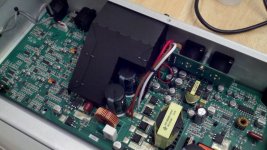
The pulsating thing happened to me too, one of the output filter capacitors failed shorted and the amp kept cycling due to the short. I replaced all the output filter capacitors and everything worked fine.
You should build one box and then measure both drivers in it.
Then you can adjust the frequency divider and equalize.
Then you can adjust the frequency divider and equalize.
The thing about open outputs has been reported many times. Some tell you it should be no problem. Reality is telling you something else.
From a theoretical approach, it should e possible to leave outputs open. I have no idea why it leads to problems in practice. Anyway, it is easy to put some 10-30 Ohm 1W resistors at the outputs until you connect speakers.
If you are the explorer personality, check all output devices, maybe one failed. Probably a "save money" problem, made in China. Just now they sell fake face masks for medical professionals to the world, do you think these personalities have any problem to put a to weak cap into an amp?
Hi Guys!
So, I am still going with this. I got hacked off for a while and then recently came back to it!
I have run in to problem tho and I wonder if anyone could advise, please?
All is up and running, crossover, volume, DAC etc. The problem is with the DAC output though. It has intermitant clicks/pops when the volume of the DSP board is turned up.
I have done all checks I can possibly think of including changing PSU to the amp, DSP and DAC. I have swapped coupling caps and I have chased it down to coming from the DAC as it is present when the DAC output goes to other amp channels not just the sub channel. I have tried a blank sigma project with low data load, no dice.
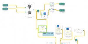
The set up is 3E DSP board with 4 outputs going to amp and then the 3E board is also outputting data to a PCM5102 DAC (as Ed very kindly outlined here). The popping starts immediately rather than in increased volume so that suggests to me that it is a data issue.
The stereo DAC is set up so it is outputting mono to both channels but one is inverted to create a balanced signal to go to the sub portion of the amp. The outputs are then parralelled to each of the 2 sub amp inputs. I have attached images and the project file.
Can anyone suggest a reason why ths might be happening? I am so close to finishing!
Cheers guys and hope you are all well.
G.
So, I am still going with this. I got hacked off for a while and then recently came back to it!
I have run in to problem tho and I wonder if anyone could advise, please?
All is up and running, crossover, volume, DAC etc. The problem is with the DAC output though. It has intermitant clicks/pops when the volume of the DSP board is turned up.
I have done all checks I can possibly think of including changing PSU to the amp, DSP and DAC. I have swapped coupling caps and I have chased it down to coming from the DAC as it is present when the DAC output goes to other amp channels not just the sub channel. I have tried a blank sigma project with low data load, no dice.
The set up is 3E DSP board with 4 outputs going to amp and then the 3E board is also outputting data to a PCM5102 DAC (as Ed very kindly outlined here). The popping starts immediately rather than in increased volume so that suggests to me that it is a data issue.
The stereo DAC is set up so it is outputting mono to both channels but one is inverted to create a balanced signal to go to the sub portion of the amp. The outputs are then parralelled to each of the 2 sub amp inputs. I have attached images and the project file.
Can anyone suggest a reason why ths might be happening? I am so close to finishing!
Cheers guys and hope you are all well.
G.
Attachments
Satellites done.
I missed this when it was posted, but these look superb, well done.
What is the finish on the central MDF panel?
Are the ports just holes, or is there a length of tube behind?
Cheers man.
The whole speaker was first coated in a couple of coats of Rustoluem Crystal Clear satin then an acrylic colour over the top of the MDF sections then several more coats of crystal clear. over everything. I know the paint isn't very strong but I have used the crystal clear on my coffee table that has taken a pounding over the past two years and it is doing well.
The port is tuned to around 90hz I think so quite short but it looks shallow because i use PVC pipe into a forstner bit cut hole behind the port front, does that make sense? The port fits in snugly to the baffle from behind.
- Home
- Amplifiers
- Class D
- 6 Channel TPA3116 + DSP