The LMC7660 is commonly used in electric guitar effects pedals to generate a negative supply, similar to what you are proposing here. The question for hifi use is whether you can sufficiently filter out the switching noise, both from the gate bias of the SIT and from the main power rail. Noise injected into either of those places would potentially have adverse effects in the sound of your amp.
It is important to know what the OSC frequency, or range of frequencies, is. That would determine the most effective techniques for filtering the unwanted noise. For example, typical practice in effects pedals would use a pair of 100 nF ceramic caps, plus a 10 uF tantalum cap close to the VOUT pin of the inverter. The 220 uF cap would remain to filter the main +V supply, but its location is less critical.
Be aware that if the OSC frequency tends to drift, then that rate of drift is itself a noise component that needs to be filtered. In my previous profession, the output of a switching inverter such as the LMC7660 would be fed to a linear regulator to reduce the switching noise to an acceptable level. For the purpose of this amplifier, the common TL431 regulator may work well. In other words, the switching inverter takes the place of a small power transformer + rectifier + filter caps.
Last edited:
Thank you for the suggestions, always appreciated 🙂
I was originally thinking along the lines of a diode pump/doubler, then thought that the noise would be easier to filter if it was higher, the oscillator runs at 10KHz. The datasheet recommended regulator LP2951 doesn't look bad, i'll chew it over a bit more.
I like the idea of adding another winding 😎 but i'm lazy, I'd probably just use another transformer 😀
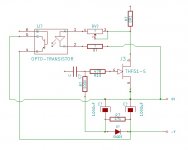
Had another thought earlier (it always hurts when that happens), the bias, what is it actually doing? - adjusting Vd; rather than 'grid bias', why not 'cathode bias' or not quite - monitor Vd with an opto and shunt the bias; iv'e done a scribble, but 'me brain' is too tired to check it for mistakes.
bias - circuit in 50W-SE-Schade-amp
Before I started my build I was thinking a lot about the bias - circuit in this amp.
I saw the TL431 - version (looks nice because of its little parts count).
I remember that Nelson Pass also said, that a battery-version with regulator could be used.
I thought: battery - version could have very low noise - but you have to recharge your battery. Hmmm🙄
Then I build a completely seperated PSU for the bias - voltage:
(yes, I know: so many parts for the bias - voltage...).
Trafo 230 V~/ 50 Hz (prim.) to 2 x 6V~ (sec.) - bridge-rectifier - CRCRC-filter (voltage is 18,2 V after the filter) - LM317AT regulator ( I know, it is an
oldtimer and noisy, LT1083 could have been used also).
My fear was: does my bias circuit start as fast as the main PSU so that the
lower MosFet in the schematic 'comes alive'?
I only can say it works. The upper MosFet is faster ( it gets close to full rails voltage at start-up and then the lower MosFet comes alive and they balance in)
But I use two IXYS- MosFets (positive bias - voltage). It should work also if
you use a THF-51 (negative bias -voltage). Only reverse polarity and reference to audio-ground. Or you could make a PSU with negative voltage (LM337).
That is what I did. Perhaps you think that's a dumb solution?
And yes: I want to get that 'crown of dumbness' 😀
Greets
Dirk
.......
And yes: I want to get that 'crown of dumbness' 😀
Greets
Dirk
it can't be much simpler than I did in Singing Bush series ..... and it's effective enough
regarding Dumbness ....... no way - there is Pico ......... and he's only Second


Mornin',
Picture for reference, re bias.
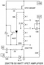
Looking at the the CCS, the LED is monitoring the voltage across the resistor string, if the string voltage increases the opto transistor starves the FET of gate voltage, hence the CC action, the opto cap is used to swamps the modulation.
2 points to me for teaching my grandmother to suck eggs.
I'm suggesting the same technique could used to monitor and set Vd.
Sorry Dirk, the crown will be mine 😀
Picture for reference, re bias.
Looking at the the CCS, the LED is monitoring the voltage across the resistor string, if the string voltage increases the opto transistor starves the FET of gate voltage, hence the CC action, the opto cap is used to swamps the modulation.
2 points to me for teaching my grandmother to suck eggs.
I'm suggesting the same technique could used to monitor and set Vd.
Sorry Dirk, the crown will be mine 😀
Attachments
it can't be much simpler than I did in Singing Bush series ..... and it's effective enough...
I like the way you did it, very smart

Thanks for the feedback ZM.
Why is it that you spot the mistake after uploading, the opto emitter should connect to the diode anode, more dumb point for me 😀
Why is it that you spot the mistake after uploading, the opto emitter should connect to the diode anode, more dumb point for me 😀
on the phone now,so lazy to follow details... but I did saw just opto...
from my musings and extended sims , I know that in some arrangements you need tighter regulation,meaning more gain.... which calls for some additional gain cell,easiest done with OP
from my musings and extended sims , I know that in some arrangements you need tighter regulation,meaning more gain.... which calls for some additional gain cell,easiest done with OP
I'll breadboard something, see if I can get it to work, luckily I have some IXTH16N50D2 to play with 
Last edited:
I am choosing up between mono blocks or a super long case (700mm) with 2 of those heatsinks on each side.
...the opto emitter should connect to the diode anode...
That's wrong too, 😱 should be the collector to the diode anode.
I think either my remaining half dead brain cell has kicked the bucket, or the java is caffeine free 🙁
Bonjour à vous tous.
Pour l’achat de THF -51S, ce fournisseur (pras1170 ) est-il fiable sur ebay ?
Merci à l’avance de vos commentaires. 1pcs NOS THF-51S THF51S TOKIN V-FET(SIT) NEW japan | eBay
Pour l’achat de THF -51S, ce fournisseur (pras1170 ) est-il fiable sur ebay ?
Merci à l’avance de vos commentaires. 1pcs NOS THF-51S THF51S TOKIN V-FET(SIT) NEW japan | eBay
I will try...this amp
Hello members,
yesterday evening I had an exciting experience. One monoblock made 'interesting' things...🙄
I tested another preamp (ZEN balanced line stage) together with the 50W-SE-Schade- amp. I had a lot of hum and tried to dial the pots at the pre as well at the poweramp. suddenly the bias was running away - up, up and away.
I immediately switched off.
I pulled the amp off for an inspection. Crazy measurements on my DMMs
(Very high voltages at both MosFets).
Today I pulled off the optocouplerboard. After disconnection of all wires from the upper MosFet I tested it for failures - still o.K.! - Pooh! 😱
Then I thought, what could be damaged?
My first suspicion - optocoupler (all the rest are a few resistors, caps,...)
and yes, it was that tiny little 'creature'. I had two ones as spare (was it presentiment?). Repaired and running again. 😉
Don't ask me for the reason?
Greets
Dirk
happy listener again...
Attachments
- Home
- Amplifiers
- Pass Labs
- 50w Single-Ended BAF2015 Schade Enabled