I tested the PSU with nothing hangin' on it. Put the light-bulb-tester in. Light turned off - pooh! Then without light-bulb-tester: I was short to a big boom!
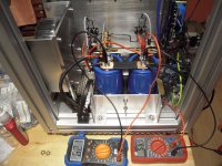
I've got 73.8 V on the second cap. I made a CRC - filter with 2 x 47000µF caps.
The big cans / caps are rated at 80 V - so, I was close to the max. 🙄
But my mistake - I bought the wrong transformers.
230 V~ prim. / 2 x 25 V~ sec. / 500 W
sec. in series = 50 V~
50 V~ x 1.2 = 60 V
50 V~ x 1.3 = 65 V (this was what I've expected by the rule of thumb).
But the transformers put out a bit more than 2 x 25 V~ sec. (o.k. - unloaded).
I am searching.
And I will try to get the dumbness crown!
Greets
Dirk 😀

Hello Soundhappy,
the transformers are from the german company 'Strobelt'.
Strobelt - Ringkerntransformator Steuertransformator Trafogehause
They are only 40km away from where I live.
The trafos are in spec.. But I should have bought 2 x 22V~ sec. ?
Greets
Dirk
You are probably ok with your transformer as your test was with no load.
I have Antek 2 x 50V secondaries in parallel, 600VA, and under load I am getting about 62.5V.
On another note, it's good to see a flurry of activity with more amps being built.
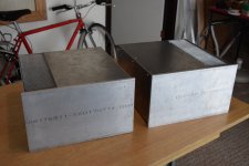
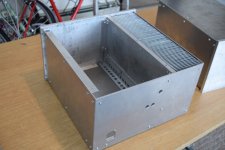
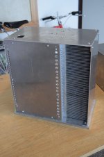
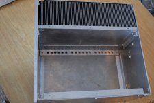
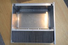
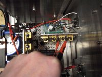
I finally finished the two amp cases. Well, almost finished. Still need to drill some vent holes in the top plates. Also, more vent holes in the bottom plates once the mounting holes for the electronics have been drilled. And, some sanding and polishing.
However, I am glad it's mostly done. Many hours and lots of aluminum chips produced.
Now, onto the fun part!
However, I am glad it's mostly done. Many hours and lots of aluminum chips produced.
Now, onto the fun part!
Attachments
Last edited:

I have a new idea for this circuit.
Not sure if anyone has already tried it, I haven’t been following the thread for a very long time, but will post something later.
Not sure if anyone has already tried it, I haven’t been following the thread for a very long time, but will post something later.
I’m going to build this after I’m done with my Penultimate Zen V4. The Zen has been on my build list since I started working on my ACA mods. I’ve always considered it to be the big brother of the smaller amp, so I really want to hear what it sounds like. This will re-use a pair of 48V EI transformers from the old Hafler amps that I’ve collected and rebuilt over the last couple years.
After that, it’s the 50W single-ended BAF2015 design, including both the Schade feedback version and a 2SK182ES version. I’ll be building a pair of monoblocks with Plitron 625VA, 50V transformers. I like the idea of of having 50+ Watts of class A available. I plan to spend some time finding the “sweet spot” of the 2SK182ES SITs.
After that, it’s the 50W single-ended BAF2015 design, including both the Schade feedback version and a 2SK182ES version. I’ll be building a pair of monoblocks with Plitron 625VA, 50V transformers. I like the idea of of having 50+ Watts of class A available. I plan to spend some time finding the “sweet spot” of the 2SK182ES SITs.
My Mouser order including the IXFN140N20P "hockey pucks" arrived yesterday, and the 2SK182ES SITs should be arriving tomorrow. Being able to use either of these in a single build will be challenging, hopefully in a good way. The upper Mosfet used as the current source should be fine with the 4N37 biasing scheme. The lower part of the amp circuit will need something different for each type of device. At this point, it looks like it would be best to fabricate two different boards.
I already have a pair of Lundahl LL1540 signal transformers for the Schade feedback varaiant. I suspect that my spare LM329 references can be used for the Vgs voltage reference. Perhaps a little green LED in series with the LM329 will give a favorable tempco for the big IXYS part.
Since I don't have the SITs in hand yet, I don't know what their bias voltage will be. Do these tend to go negative Vgs? I want to give myself some room to find with sweet spot with respect to bias current and Vgs operating point.
The 2SK182ES is a n-channel depletion mode device - negative Vgs is needed to turn the device off. Unfortunately it seems that there is wide variability in Vgs among SITs so you'll need to test them in order to find what voltage range you need to provide in your bias supply.
My THF-51Ss were in the neighbourhood of -3.0V for 3.3A at 29V, but I have read that THFs range from -1V or so to -4V and higher. I don't know where the 2SK182 stands though.
My THF-51Ss were in the neighbourhood of -3.0V for 3.3A at 29V, but I have read that THFs range from -1V or so to -4V and higher. I don't know where the 2SK182 stands though.
I will try...this amp
Good evening!
And it is a good evening....
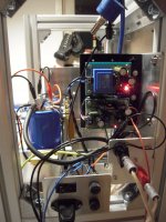
I made the first start up this evening with the 50W- SE- Schade-amp.
It is alive . No fire
  !
!
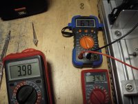
I've got the following values:
Rail: 67,3 V
Mid between MosFets: 34,7 V
Bias voltage into transformer: 3,98 V
temperatures hockeypucks: 68° C / 69° C
'' heatsink: 53,6° C / 53,8° C
Doesn't look so bad till now! 😀
Cheers Dirk
Good evening!
And it is a good evening....
I made the first start up this evening with the 50W- SE- Schade-amp.
It is alive
. No fire !I've got the following values:
Rail: 67,3 V
Mid between MosFets: 34,7 V
Bias voltage into transformer: 3,98 V
temperatures hockeypucks: 68° C / 69° C
'' heatsink: 53,6° C / 53,8° C
Doesn't look so bad till now! 😀
Cheers Dirk

to Ben Mah
I forgot to write down the voltage over the resistor. 🙄
I will measure again (perhaps today - after work).
Greets
Dirk
I forgot to write down the voltage over the resistor. 🙄
I will measure again (perhaps today - after work).
Greets
Dirk
to ItsAllInMyHead and Pinholer
Thanks for the kind words! 😀
for pinholer:
temperature on the MosFets (directly): 68° C / 69° C
temperature on the heatsink: 53,6° C / 53,8° C
(from outside / position where hockeypuck is inside).
Have anice day!
Dirk
Thanks for the kind words! 😀
for pinholer:
temperature on the MosFets (directly): 68° C / 69° C
temperature on the heatsink: 53,6° C / 53,8° C
(from outside / position where hockeypuck is inside).
Have anice day!
Dirk
Thanks for the info, Dirk. Your large heatsinks are working well. I spent a lot of time thinking about how to dissipate the heat before deciding to go with fans. Each has its good and bad points. In the end, the smaller heatsink size decided it for me.
to Ben Mah #1012
Hello Ben Mah,
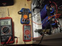
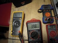
I measured 315mV (0.315 V) over one 0.1 Ohm resistor (between B and C).
so if I am not wrong: I = U/R
I = 0.315V / 0.1 Ohm
I = 3.15 A.
Greets
Dirk
Hello Ben Mah,
I measured 315mV (0.315 V) over one 0.1 Ohm resistor (between B and C).
so if I am not wrong: I = U/R
I = 0.315V / 0.1 Ohm
I = 3.15 A.
Greets
Dirk
Hi Dirk,
3.15A is good. I also see 3.98V and 40.1V, and in an earlier photo I see 3.98V and 34.7V. I assume that those are Vgs and V between 0.1R at drain above the lower IXFN and source of the lower IFXN. If that is the case, try adjusting Vgs so that both channels have the same voltage drop across the lower IXFN.
Ben
- Home
- Amplifiers
- Pass Labs
- 50w Single-Ended BAF2015 Schade Enabled