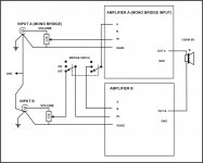
thank u man i want to builb this but i am not sure what should be connected on ponits A and B, and PRO. please help i need this cct
Point A and B is only for bridge mode, and PRO connect to PRO pin on PA protect. Amp will work without connect A, B and PRO pins.
Regards
hey im looking for basicly the same type of amp but with a rail V of 45v+-i fix alot of amps and sometimes they are burned so badly and i need to build my own amps now. most of the amps i repair run with 45 - 50v can you maybe help me out please?
Kind regards
Kind regards
hey im looking for basicly the same type of amp but with a rail V of 45v+-i fix alot of amps and sometimes they are burned so badly and i need to build my own amps now. most of the amps i repair run with 45 - 50v can you maybe help me out please?
Kind regards
For +/50V rail go to: http://www.diyaudio.com/forums/solid-state/164093-100w-ultimate-fidelity-amplifier-59.html
Hy! I post some pics, comment it if you want.
Apex: I modified the protect board, i hope you don't mind. I used my favorite relay, and so the board needed to be modified.
I also made a psu, 80.000uf/100V total, i hope this is enough for 2 of this B500 amplifiers.
View attachment 188639
View attachment 188640
View attachment 188641
View attachment 188642
View attachment 188643
View attachment 188644
View attachment 188645
View attachment 188646
which power supply do u use?can u share the layout and top.
![APEX%20H900%20Bridge%20Wireing[1].jpg](/community/data/attachments/190/190924-6248eaa9232bb398dc7ad9317671f86a.jpg?hash=YkjqqSMrs5)
My PSU PCB
Hy! I am really happy, that someone is interested in my work, as soon as i get home from work, i can attach the PSU PCB in sprint layout format (.lay) 😎
which power supply do u use?can u share the layout and top.
Hy! I am really happy, that someone is interested in my work, as soon as i get home from work, i can attach the PSU PCB in sprint layout format (.lay) 😎
Psu lay
Hy! Here it is as i promised.
I used the diode bridge as shown on the picture

View attachment psu.zip
It is very simple, as you can see, only 1 diode bridge, fuse holder, capacitor bank and 2x100nF/100V at the end.
which power supply do u use?can u share the layout and top.
Hy! Here it is as i promised.
I used the diode bridge as shown on the picture
View attachment psu.zip
It is very simple, as you can see, only 1 diode bridge, fuse holder, capacitor bank and 2x100nF/100V at the end.
Transformer soft start
Hy! I will post the transformer soft start circuit here, because it may be useful for everyone.
View attachment lagyindito.zip
which power supply do u use?can u share the layout and top.
Hy! I will post the transformer soft start circuit here, because it may be useful for everyone.
View attachment lagyindito.zip

Hi.
with the knob towards the operator and the 3 connections pointing down, you have a pot that gets quieter as you turn the knob clockwise.
Most listeners prefer clockwise for louder. This requires you to swap common (Sig Gnd with Input)
You can "see" this mechanically.
Turn the knob fully anticlockwise. The wiper will now be positioned at the stop next to Input. Wiper taps off maximum signal level (=loud).
Turn the pot fully clockwise till the wiper hits the Common stop. The wiper now taps off a near ground signal level (=quiet)
Hi.
with the knob towards the operator and the 3 connections pointing down, you have a pot that gets quieter as you turn the knob clockwise.
Most listeners prefer clockwise for louder. This requires you to swap common (Sig Gnd with Input)
You can "see" this mechanically.
Turn the knob fully anticlockwise. The wiper will now be positioned at the stop next to Input. Wiper taps off maximum signal level (=loud).
Turn the pot fully clockwise till the wiper hits the Common stop. The wiper now taps off a near ground signal level (=quiet)
is this correct?
Attachments


Volume pot
apex,
how to use volume pots in a balanced input amp(like b500 in grouond A+B )🙂
apex,
how to use volume pots in a balanced input amp(like b500 in grouond A+B )🙂
A, B pins are for bridge no for balanced input, go to post #54.
A, B pins are for bridge no for balanced input, go to post #54.
sir,
not this bridge,
but i mean balance input using one channel only grnd,a,b
Attachments
sir,
not this bridge,
but i mean balance input using one channel only grnd,a,b
A and B pins can not be use as balanced input without change schematic.
thanks apex,
the zy15 and zf15=is it ok to use for this two value boyh 1watt?
the 25v 2.2uf,47uf,electrolytic=is it ok to use higher v with same uf?
the zy15 and zf15=is it ok to use for this two value boyh 1watt?
the 25v 2.2uf,47uf,electrolytic=is it ok to use higher v with same uf?
- Home
- Amplifiers
- Solid State
- 500W PA amplifier with Limiter