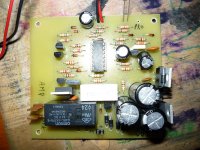
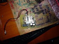
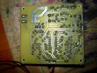
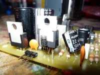
eesbiboy,
my friend abandon TLO step driver,
no success tlo story so far.
thanks
for the advice engel...
regards
ees...
Got the PS sorted out. Getting +/- 49.7 volts DC, grounding the two black secondary wires . Reading across the two DC outputs I get 137 volts; don't really understand why. Seems like it would be 100. Oh well, I'm moving ahead. If I could just remember where I put the protection board. Need to rig up a light bulb too.
Hi Fpaul,
have you got a backup voltmeter?
Check the output voltages again.
137Vdc & +-49.7Vdc cannot both be right.
have you got a backup voltmeter?
Check the output voltages again.
137Vdc & +-49.7Vdc cannot both be right.
Thanks for the input Andrew, turns out it was because the psu board wasn't grounded. I'm getting +/- 68 and 136 after grounding the board. Hooked up the protect board and I'm getting +/- 14.9 volts and 30 on that. Just need to finish tapping out my heat sink and mounting the main board and I should be ready for a test soon. I've broken two taps so far; not used to doing heat sinks. Just have two holes left to do though.
I've broken two taps so far; not used to doing heat sinks. Just have two holes left to do though.
You need to use oil (cutting oil preferably) with taps or they snap easy.
Also dont go too far at once, do a turn or so then back up a bit.
irvy my amp now work.the problem is at 2n5501 base pin not connected to copper trace.very hard full to find this mistake.thank you for helping me.can you suggest high quality tone control or pre amp and subwoofer amplifier>maybe you have problem with your wiring,, i run B500 on trapo 55vac -/+75 work fine no problem
@MAMAK go find here
http://www.diyaudio.com/forums/solid-state/167363-mic-line-eq-preamps.html
http://www.diyaudio.com/forums/solid-state/167363-mic-line-eq-preamps.html
Last edited:
You need to use oil (cutting oil preferably) with taps or they snap easy.
Also dont go too far at once, do a turn or so then back up a bit.
That worked much better. Thanks!
threading aluminium
one whole turn forward (I usually do 3 half turns) and quarter turn back (or more) until you feel the swarf breaking off. Then forward again.
My cutting oils are out in the garage/workshop. I keep a tiny bit of vegetable oil with my taps for tapping aluminium.
one whole turn forward (I usually do 3 half turns) and quarter turn back (or more) until you feel the swarf breaking off. Then forward again.
My cutting oils are out in the garage/workshop. I keep a tiny bit of vegetable oil with my taps for tapping aluminium.
Hello Apexaudio,
I have read the threads for the H900 and your B500 amp. I'm interested to build the B500.
To start with, I have simulated the circuit using Multisim 10 (Like most of my amplifiers before they made it to production and construction.) However, the output signal of the B500 is 180 degrees out of phase.
Here are the values I've used:
Voltage rail: +/-90VDC
Input Voltage: 500mv @ 1KHz, 0 Deg.
Output Voltage: 50V peak to peak @ 1KHz, 180 Deg.
The amplification is quite good considering the ratio is 1:10. I will post the screenshots and the test results here soon.
Is there something that I did wrong? I have check the input stage of the opamps. BTW I used the TL072 instead of NE5532. Please enlighten me.
Thanks,
Blueice23
Input Voltage: 500mv @ 1KHz, 0 Deg.
Output Voltage: 50V peak to peak @ 1KHz, 180 Deg.
The amplification is quite good considering the ratio is 1:10
are you comparing apples to spiders?the amplification ratio should be 1:100
500mVac input signal and 50Vpp output signal are neither 1:10 nor 1:100.
You must convert the voltage measurements so that you are looking at apples only.
are you comparing apples to spiders?
500mVac input signal and 50Vpp output signal are neither 1:10 nor 1:100.
You must convert the voltage measurements so that you are looking at apples only.
Simple maths sometimes is very difficult for others........
😀😀😀😀
Hello Apexaudio,
I have read the threads for the H900 and your B500 amp. I'm interested to build the B500.
To start with, I have simulated the circuit using Multisim 10 (Like most of my amplifiers before they made it to production and construction.) However, the output signal of the B500 is 180 degrees out of phase.
Here are the values I've used:
Voltage rail: +/-90VDC
Input Voltage: 500mv @ 1KHz, 0 Deg.
Output Voltage: 50V peak to peak @ 1KHz, 180 Deg.
The amplification is quite good considering the ratio is 1:10. I will post the screenshots and the test results here soon.
Is there something that I did wrong? I have check the input stage of the opamps. BTW I used the TL072 instead of NE5532. Please enlighten me.
Thanks,
Blueice23
Limiter circuit around IC1a inverting phase and give extra gain to amp, use this circuit without limiter for simulation.
Regards
Attachments
Update, ladies and gentleman!
I bought a few 7815's, their manufacturer is National, and thrown away those annoying TaiwanSemi ones. Results: No malfunction so far, yesterday turned on/off sequentally the circuit (with 10s delays) for about 10 minutes. Everything seems to work very well. So i'm happy so far. I'll make other tests today, i'll keep you informed.
I bought a few 7815's, their manufacturer is National, and thrown away those annoying TaiwanSemi ones. Results: No malfunction so far, yesterday turned on/off sequentally the circuit (with 10s delays) for about 10 minutes. Everything seems to work very well. So i'm happy so far. I'll make other tests today, i'll keep you informed.
There are many times I think parents forget to tell their children why they go to school. Part of that very long list of reasons is to learn how to live and work in the community. In this case "working" is the DIYaudio hobby.Simple maths sometimes is very difficult for others........
In this case "working" is the DIYaudio hobby.
Have you got a contract of "correcting mistakes of others" from variac and party 😀
are you comparing apples to spiders?
500mVac input signal and 50Vpp output signal are neither 1:10 nor 1:100.
You must convert the voltage measurements so that you are looking at apples only.
Are you trying to get smart? I do believe your apple came from a mango tree!
Try using the Multisim software so that you will know what I'm talking about! 😛😛😛
Voltage measurement were generated by the system and not calculated!
Simple maths sometimes is very difficult for others........
😀😀😀😀
While others are barking on the wrong tree at times they're standing on their head! 😛😛😛😛
Try to see clearly dude....
- Home
- Amplifiers
- Solid State
- 500W PA amplifier with Limiter


