8XTDA1541A nos dac tower
http://img176.imageshack.us/i/65886714.jpg/
http://img22.imageshack.us/i/47400734.jpg/
http://img204.imageshack.us/i/93533065.jpg/
http://img219.imageshack.us/i/77759119.jpg/
http://img204.imageshack.us/i/83122405.jpg/
http://img521.imageshack.us/i/60245050.jpg/
An externally hosted image should be here but it was not working when we last tested it.
http://img176.imageshack.us/i/65886714.jpg/
http://img22.imageshack.us/i/47400734.jpg/
http://img204.imageshack.us/i/93533065.jpg/
http://img219.imageshack.us/i/77759119.jpg/
http://img204.imageshack.us/i/83122405.jpg/
http://img521.imageshack.us/i/60245050.jpg/
Hi Dvb,
Hows the sound of the Lampizator with 6n2p ?
Have you tried with 1 tda & 2 tda . If so how much
difference is it sound wise ?
TQ
Hows the sound of the Lampizator with 6n2p ?
Have you tried with 1 tda & 2 tda . If so how much
difference is it sound wise ?
TQ
Noyan,
Is there a big sound difference compare with 4X?
Did you tried with EC's latest dem clock?
Is there a big sound difference compare with 4X?
Did you tried with EC's latest dem clock?
JC951t said:Hi Dvb,
Hows the sound of the Lampizator with 6n2p ?
Have you tried with 1 tda & 2 tda . If so how much
difference is it sound wise ?
TQ
With the delivered parts on the DAC and the Lampizator SRPP circuit with 6N2P (Dale RN55 I/V resistor), it plays equal to my PS Audio DL III with Cullen Circuit Stage IV Mod.
And this is a realy goood one.
Now, with the Black Gate 100µF N-Type on the 3 powerlines, 0,47µF NX HQ-Type for decoupling and 0,1µF NX HQ-Type bypassing each of the 7 regulator outputs, it plays in another league!

Next tweeks are:
- PS with Tube recifier (6X4) for the HV of the 6N2P
- I/V resistor change to TX2575 Naked Bulk Metal “Z” Foil
I think, that´s it. 🙄
I only run the DAC with all 4 TDA´s. So i couldn´t say anything about the difference to 1 or 2 TDA´s.
Best
dvb-projekt
8XTDA1541A nos dac tower
Hi fastvideo,
I am charging the DAC`s batteries at the moment. I am planning to listen it`s sound tonight then i will write the listening impression.
Noyan
Hi fastvideo,
I am charging the DAC`s batteries at the moment. I am planning to listen it`s sound tonight then i will write the listening impression.
Noyan
Hi Dvb,
Thanks . Hey re 0.47 BG NX, are you using them on
the decoupling pins of the TDA ? How's the highs
by the way ?
Many thanks
Thanks . Hey re 0.47 BG NX, are you using them on
the decoupling pins of the TDA ? How's the highs
by the way ?
Many thanks
Yes.
The are soldered under the PCB´s.
If you look carefully on the second picture of my board above, you could see them 🙂
The are soldered under the PCB´s.
If you look carefully on the second picture of my board above, you could see them 🙂
I tried the 6n2p option with one tda1541 and I can tell that I prefer by far the alternative with D3a or e280F triode connected,150V 10mA choke loaded,
5852 Bendix rectification,it yields a much more open sound very sharp and smooth, passive I/V resistors 33 ohms...
I much encourage people to have a try.
5852 Bendix rectification,it yields a much more open sound very sharp and smooth, passive I/V resistors 33 ohms...
I much encourage people to have a try.
Hi Devas,
Are you using 2.2.uf decoupling caps as per Lukas
design ? D3A is difficult to find at my end. I have
a couple of 6n2p at hand. Perhaps a choke or ccs
loaded 6n2p might sound better.
Thanks
Are you using 2.2.uf decoupling caps as per Lukas
design ? D3A is difficult to find at my end. I have
a couple of 6n2p at hand. Perhaps a choke or ccs
loaded 6n2p might sound better.
Thanks
yes 2,2µF is fine.
Alternatively you can try e180f, anyway all the tubes mentionned are regularly available on ebay and quite cheap to boot, 5842 is another option too.
I tried a lot of tube output stages for the TDA1541 and to my taste D3a beats them all.
Alternatively you can try e180f, anyway all the tubes mentionned are regularly available on ebay and quite cheap to boot, 5842 is another option too.
I tried a lot of tube output stages for the TDA1541 and to my taste D3a beats them all.
Well I did not remove the 470pF caps, they are still in the circuits.... I just tied pin 16 back of 3 slaves to pin 16 the nominated master pin 16 with 100pF cap. It seemed to improved the sound, imaginary or not.... 🙂
One of my next mods is a total DEM reclock, like you talk through.
jk
One of my next mods is a total DEM reclock, like you talk through.
jk
-ecdesigns- said:
Unfortunately you can't slave TDA1541A DEM oscillators this way. When you remove the 470pF caps from the other 3 TDA1541A chips, the DEM oscillators of these chips will oscillate at maximum frequency (around 7 MHz) due to stray capacitance. This frequency will simply inter-modulate with the approx. 250 KHz DEM oscillator from the master.
The following problems have to be solved:
....
....
....
....
This way all TDA1541A chip DEM oscillators can be clocked synchronously.
Hi DVB-projekt,
Good to hear that the tweaks are working out! Also your pics are very good.
What torroids have you used for the PSU of the DAC and the Lampizator?
Cheers,
Mark.
Good to hear that the tweaks are working out! Also your pics are very good.
What torroids have you used for the PSU of the DAC and the Lampizator?
Cheers,
Mark.
 work for the next weekend....
The new I/V resistors TX2575 from Texas Components arrived today!
An externally hosted image should be here but it was not working when we last tested it.
An externally hosted image should be here but it was not working when we last tested it.
An externally hosted image should be here but it was not working when we last tested it.
I will also do the Tube rectifier upgrade for B+ of the 6N2P, with:
- 6X4 Tung Sol rectifier
- CRC Filter with Mundorf TubeCap´s
- new Tentlabs E-Choke
So, let´s see.....

Thanks Oliver!
Could you drop me an email? I am not a full member yet and can't reach you on yours (yet). I have a few off topic questions.
Cheers,
Mark.
Could you drop me an email? I am not a full member yet and can't reach you on yours (yet). I have a few off topic questions.
Cheers,
Mark.
DEM RECLOCK
Hi John,
in Post 35 and the attached Schematic you are powering the inverter IC with 10v derived from the -5 and -15v lines.
I am using a differential line driver (DS8921) to create the balanced DEM clock signals, which is powered by +5v. Is it worth me powering the DS8921 chip with the -5 and -15 power in the same way to create the negative offset in the DEM reclock signals?
Brad
in Post 35 and the attached Schematic you are powering the inverter IC with 10v derived from the -5 and -15v lines.
No it runs on approx. 5V DC (-5V minus voltage drop across 5.1V Zener diode D1). So the 74HC00 GND connects to -15V and the plus connects to approx. -10V.
The DS8921 can also be used, but it might require a separate voltage regulator:
UA7805, input to -5V, GND to -15V (creates positive 10V input voltage with respect to GND pin), output then provides +5V with respect to -15V supply.
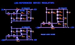
But it's better to use the discrete LED referenced power supplies (much better sonic performance compared to 78/79xx regulators). I attached schematics of these LED referenced voltage regulators (+5V, -5V, and -15V).
For the DEM clock mod you would need two of these +5V regulators.
Attachments
So my friends... The first work is done. 🙂
Changing the Lampizator rectifier circuit to a real good tube rectifier circuit with the new Tentlabs Electronic-Choke.
My circuit based on the Tungsol 6X4WA, with separate transformer for the heater,
with the new Tentlabs e-choke module
As recommended i change the input capacitor from 330µF to a 10µF TubeCap (MKP) from Mundorf.
The module replaced a normal iron choke and offers up to 60dB supply ripple reduction.
The output capacitor after the e-choke must be a 330µF (in my case the original one).
The last two caps are also Mundorf TubeCaps 10µF.
Here the actual complete DAC:
Tomorrow i would like to change the last parts:
- Input circuit caps to OSCON Caps
- I/V resistor change
That´s it... 😀 Ohh, i forgot the case. I have this ready in my mind but it will take a while.
@ Markuzz:
Please ask the board admin for help, because i couldn´t mail (only to full members).
Changing the Lampizator rectifier circuit to a real good tube rectifier circuit with the new Tentlabs Electronic-Choke.
My circuit based on the Tungsol 6X4WA, with separate transformer for the heater,
An externally hosted image should be here but it was not working when we last tested it.
An externally hosted image should be here but it was not working when we last tested it.
with the new Tentlabs e-choke module
An externally hosted image should be here but it was not working when we last tested it.
As recommended i change the input capacitor from 330µF to a 10µF TubeCap (MKP) from Mundorf.
The module replaced a normal iron choke and offers up to 60dB supply ripple reduction.
The output capacitor after the e-choke must be a 330µF (in my case the original one).
The last two caps are also Mundorf TubeCaps 10µF.
An externally hosted image should be here but it was not working when we last tested it.
Here the actual complete DAC:
An externally hosted image should be here but it was not working when we last tested it.
Tomorrow i would like to change the last parts:
- Input circuit caps to OSCON Caps
- I/V resistor change
That´s it... 😀 Ohh, i forgot the case. I have this ready in my mind but it will take a while.
@ Markuzz:
Please ask the board admin for help, because i couldn´t mail (only to full members).
- Home
- Source & Line
- Digital Line Level
- 4xtda1541a Nos Dac Project