Rod,Yes, that's correct for the V9 Regulator. With low current (325mA) it's OK if the voltage is a little higher, too.
Do I understand correctly that it is impossible to turn on the v9 circuit without 4p1l tubes?

but let's imagine a situation where everything is already closed in a case. and I replaced the tubes but didn't put new ones in.Try to use dummy resistor (R=filament voltage/filament current) for testing.
Thank you a lot. lately, I have changed a lot in my current 4p1l preamp inspired by all your previous posts guys, and installed a Colman regulator.Andy,
If you see the EL12n datasheet, the -recommended- bias is -7.5V (250V a-c, 72mA anode, 11 mA G2 current, 90R cathode resistor), so any driver tube fulfils 15Vpp swing (about 3-5x gain).
Sample:
View attachment 1067128 View attachment 1067134
And I'm slowly going to filament bias.
@euro21
I do like your resistor-based circuit.

Unfortunately, I'm still focusing on powering 4p1l tubes with 4.2V due to the lack of the necessary power transformer and space. Please help me change the schema for 4.2V.
Simple Ohm law using.
4.2V, 0.325A filament.
If you want -about- 5..5.5V bias the filament bias resistor value:
5.5V - 2.1V (half of filament voltage)= 3.4V
3.4V/0.325A= 1.1R
If you use 1R, the estimated bias voltage is -about- 3.25+2.1= 5.35V.
The raw supply voltage of (0.325A) Rod Coleman regulator at least:
3.25V + 4.2V + 5V (R.C headroom)= 12.25V
Thanks a lot, could you please share the file for the simulation, probably i need to play a bit with THD.Simple Ohm law using.
4.2V, 0.325A filament.
If you want -about- 5..5.5V bias the filament bias resistor value:
5.5V - 2.1V (half of filament voltage)= 3.4V
3.4V/0.325A= 1.1R
If you use 1R, the estimated bias voltage is -about- 3.25+2.1= 5.35V.
The raw supply voltage of (0.325A) Rod Coleman regulator at least:
3.25V + 4.2V + 5V (R.C headroom)= 12.25V
I do not want to ask a lot of simple questions here.
Simple Ohm law using.
4.2V, 0.325A filament.
If you want -about- 5..5.5V bias the filament bias resistor value:
5.5V - 2.1V (half of filament voltage)= 3.4V
3.4V/0.325A= 1.1R
If you use 1R, the estimated bias voltage is -about- 3.25+2.1= 5.35V.
Perhaps you have an error in the calculations
3.4V/0.325A=11R. and then there will be another bias offset accordingly
Right, it was typo.Perhaps you have an error in the calculations
3.4V/0.325A=11R. and then there will be another bias offset accordingly
Not 1R, but 10R is an estimated filament bias resistor.
10R*0.325A=3.25V so another calculations are valid.
4.2V has a different connection than the 2.1V version for the Coleman regulator, as I know.Simple Ohm law using.
4.2V, 0.325A filament.
If you want -about- 5..5.5V bias the filament bias resistor value:
5.5V - 2.1V (half of filament voltage)= 3.4V
3.4V/0.325A= 1.1R
If you use 1R, the estimated bias voltage is -about- 3.25+2.1= 5.35V.
The raw supply voltage of (0.325A) Rod Coleman regulator at least:
3.25V + 4.2V + 5V (R.C headroom)= 12.25V
Bartola 4p1l
I have not found a connection in this version anywhere, everywhere they all show the connection in version 4.2V.
@Rod Coleman
Is it the right connection 4P1L + 4.2V + Filament bias?
it's only the filament with center tap.4.2V has a different connection than the 2.1V version for the Coleman regulator, as I know.
1-7 4.2V
Tied 1 and 7 - 8 2.1V
The sketched schematic is NOT filament bias device, the filament current flows between 1-7 (4.2V, 0.325A).
The tube cathode current via 11R makes (cathode) bias ... but only few hundred mV!!!
@euro21 thank you for the comment. I have changed the schema and created a new oneThe sketched schematic is NOT filament bias device
is this already correct?
(7) : 7.45V (3.25V+4.2V) Coleman Reg +
(8): Float
(1): 3.25V > 11R
My calculations relates to 10R in #1807, #1810 posts!
If you use 11R, the calculations as lower.
Really via filament bias resistor (11R) flowing the filament current + cathode current.
In this case the cathode current (about 25mA) vs. filament current (325mA) not negligible.
The correct current via filament bias resistor about 350mA.
On the 11R resistor (filament 1 pin) the voltage is 11R*0.35A= 3.85V
The voltage on filament 7 pin is 3.85+4.2= 8.05V.
If you want to use 10R, count it again, but as you can read later it's only theoretical calculation.
This -voltage on filament 7 pin- voltage can vary, depends of tube condition.
In case of worn DH tube the filament (cold, and hot too) resistance may increase (the filament thins out), but it's negligible. The important value is the filament voltage (in this case between 1-7).
If you adjust R.C. regulator to 0.325A (test it with filament bias resistor on R.C. output, set voltage V=R*I), must to check filament voltage (1-7) after few-ten minutes, and readjust R.C.
BTW in case of DH tube the -estimated- bias voltage not essential, in practice the anode current and anode voltage measuring gives the operating point.
p.s. Usually DIYers prefer 2.1V filament for 4P1L (better tone).
Last edited:
The V9 kit for 4P1L is supplied with R1 value for 4P1L with parallel-connected filaments. This gives less bias-skew for the triode curves, and should mean lower distortion.(7) : 7.45V (3.25V+4.2V) Coleman Reg +
(8): Float
(1): 3.25V > 11R
RC-V9 R1 = 1.5Ω (2,1V 650mA).
Connect:
4P1L (7) + (1) = RC-V9 FIL+ output
4P1L (8) = Fil. Bias Resistor
(0V) = RC-V9 FIL- output
For the calculations, euro21 has already given a perfect answer.
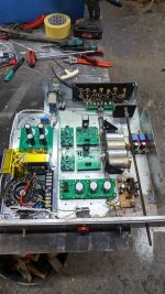
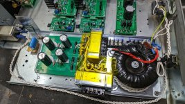
I've started putting together my 4p1l preamp. No moulds being broken here, I intend copying Ales gen 4 shamelessly, probably going to screen mode. Gyrator for the anode with Rods filament boards, and trying to keep transformers/rectifiers as far away from the signal parts as possible. Relay input switching and pot right at the back to keep paths short and hopefully address noise as much as possible. I have made up a bracket to hold the valves, it's angle brackets glued with silicone to a alu plate, and the whole thing is fixed to the base using rubber mounts. I think I'll use some ft3 in parallel giving 0.2uf for the output caps.
The transformers and filament raw DC are on a separate tray and I can mount this on some sorbothane or springs if vibration is an issue. I have a toroid for hv and two 15V transformers for the filaments.
So now to my questions:
Rod - will fixing the filament regs to the floor of the chassis (steel, thin enough) be good enough or do I need to add a thick alu plate for dissipation?
Filament bias resistor - I have some of those russian 10w 10r resistors, and was going to try a few sic diodes with them to get up to 13-14V. I see people talking about 25W resistors, but 10W seems heavy duty enough for 10r?
Attachments

I think you mean the silver ceramic ones that I use. Very nice. Just use ohms law and double or treble the wattage. These get hot.Filament bias resistor - I have some of those russian 10w 10r resistors, and was going to try a few sic diodes with them to get up to 13-14V. I see people talking about 25W resistors, but 10W seems heavy duty enough for 10r?
I tried SIC resistors. By themselves I really disliked them - harsh and artificial. They were half way good in series with a resistor, but I still objected to the edge they gave. What's wrong with filament bias? Pretty standard for a 4P1L.
Yes, they are the ones. I used these resistors in a 3a5 stage before and saw an improvement, but used the string of SIC diodes in the 01a pre. So I thought I might just use a 10r with say 3 diodes after it to get the 13-14V needed. I have to say I don't detect any sharpness with them in the 01a. I think I used 5 or 6 in series there......
I bought a few 2P29L today as well, just so that I can annoy myself into trying them in the future 🤣🤣
I bought a few 2P29L today as well, just so that I can annoy myself into trying them in the future 🤣🤣
Wise move! Very easy to power the filaments and it isn't specially microphonic.I bought a few 2P29L today as well, just so that I can annoy myself into trying them in the future 🤣🤣
Rod - will fixing the filament regs to the floor of the chassis (steel, thin enough) be good enough or do I need to add a thick alu plate for dissipation?
Heat burn for 4p1L is only 2 - 2.5W typically, so thin sheet is ok. But the interface to the transistor should be rust-free, polished smooth and flat. A very thin layer of thermal grease to finish.
Heat burn for 4p1L is only 2 - 2.5W typically, so thin sheet is ok. But the interface to the transistor should be rust-free, polished smooth and flat. A very thin layer of thermal grease to finish.
- Home
- Amplifiers
- Tubes / Valves
- 4P1L DHT Line Stage