Gate stoppers are missing on the lower FETs. Can you measure your HT supply and check ripple level?
Your custom PCB have some long paths, you may need to add cap decoupling on HT close to the mu-follower circuit (100nF to 1uF film will work)
If you can take some basic AC measurements at the filaments and anode will help.
You are not describing the filament bias arrangement nor the grounding scheme, big points to look into
PS. Don’t use my diagrams and hack them please.
Ale
Hi Mogliaa, thanks for your intervention. I answer you questions. the connections are quite short as the cards are side by side and there are 2.2 mf capacities on the gyrator cards close to the A.T. With the trimmer I can adjust the voltage shown on pin 2 of the 4pl1 from 71 volts to 56 volts. On the 10 hom R 5 I cannot read any voltage and not even any absorption of a few mill'amps
the direct voltage measured between pin 2 of the valve (output R5) and ground is 70.5 volts
while foot 2 and fil. 1-7 = 61.5 volts
foot 2 and fil. 8 = 59.3 volts
it seems that with the calculations we also find ourselves as I said at the beginning of the post the pre works but in an anomalous way with voltage of 70 instead of 153 volts on pin 2
I can say that from various tests if I want more voltage between pin 2 I should modify the 10 Mhom R6 in fact if I measure the current at the contact before the 10 mhon I have 215 volts while after 71 volts maybe if I bring it to 1mhom he managed to have the correct current by also tweaking the trimmer
Now I wonder why the R6 must have such a high value?
If I get the right currents with 2 or 1 mhom what do I compromise?
Lowering the r6 to 1mhon I get just 75 vlt in my opinion the problem lies in the M3 group and the fet J1 as M3 I used the Dn2540 while the fet I used first 2 fet in parallel 2sk170 and then with the BS170 which reaches 300 m. Amper
It may be that M3 and J1 do not release the other half of the current as released by the lnd150
can my speech be worth?
It may be that M3 and J1 do not release the other half of the current as released by the lnd150
can my speech be worth?
hi I ordered the J1 BSK111BK AND WHEN I WILL REPLACE THEM I HOPE TO GIVE GOOD NEWS SINCE THIS PROBLEM HAS NOT APPEARED TO ANY MANUFACTURER or maybe because there is no more enthusiasm for the new builders
HELLO TO ALL I WANT TO ADDRESS ANOTHER TOPIC ABOUT THE PRE with the use of pentodes and gyrators.
I have read all the posts; from 2011 to now 10 years of forum about LINE STAGE 4PL1 and I noticed that it was never talked about whether it was better to use a power supply with tube rectification or solid state with diode bridge
The expert builders will certainly be able to tell me if it is preferable to use tube or silicon in listening
it will be a matter of personal opinion or the straightening with the use of the tubes from a different sound, has no influence on the final sound. I would like an opinion from a manufacturer because he might prefer the tube instead of the silicon diode or vice versa
thank you for your opinions
My preference is mesh rectifiers like AZ1. I do also use a hybrid or Graetz bridge at times - valve on the positive and ss diodes on the negative.
I have a questions about Lundahl 1689 trafo
i use this trafo as output on my 4P1l Pre ,,i use it 18:2 (Alt.Q ) very happy with sound
But i need sometime a little more gain,,, 18:4 (Alt.P) will give that
the questions is then,,,what is the theoretically best way,for sound,
use the 18:4 or the 18:2 ?? and maybe explain why
my 4P1L is totally noise free and sound super with the 18:2
Best bjarne
Generally, the hard turn on of SS is a noise source. The various junction types have their own "fun" - PN having charge storage issues.thank you for your opinions

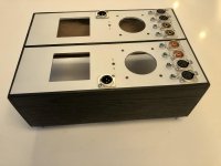
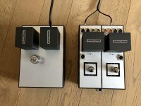
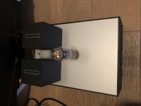
Hi Vegard
That looks amazing!
Ping me an email and I will send you a pair of ceramic Russian NOS socket to get rid of those Chinese ones which aren’t good enough [emoji3]
Such a great build deserves the best components
Ale
That looks amazing!
Ping me an email and I will send you a pair of ceramic Russian NOS socket to get rid of those Chinese ones which aren’t good enough [emoji3]
Such a great build deserves the best components
Ale
I have a questions about Lundahl 1689 trafo
i use this trafo as output on my 4P1l Pre ,,i use it 18:2 (Alt.Q ) very happy with sound
But i need sometime a little more gain,,, 18:4 (Alt.P) will give that
the questions is then,,,what is the theoretically best way,for sound,
use the 18:4 or the 18:2 ?? and maybe explain why
my 4P1L is totally noise free and sound super with the 18:2
Best bjarne
I have 1689 in my 12B4A PP line stage. I tried it as 18:2 and then tried 18:4 and liked it. It isn't the first time I've preferred a transformer with configurable windings all in series vs some in series, some in parallel. It might not be a reliable conclusion about winding configurations but it's the best I got for now.
Thanks Stephen
i have now ordered a LL1671 and will try this out,,,so i have 3 options
LL1671 as 4:1 -- LL1689 18:2 and 18: 4 so i have many good hours listen in front of me
i came across the LL1671 on page 88 in this treat,,,have no idea what is best,,must try
Best Bjarne
i have now ordered a LL1671 and will try this out,,,so i have 3 options
LL1671 as 4:1 -- LL1689 18:2 and 18: 4 so i have many good hours listen in front of me
i came across the LL1671 on page 88 in this treat,,,have no idea what is best,,must try
Best Bjarne
I was just revisiting post number 1431 and the posts following it about where to connect G3. Seems there are three options -
1. G3-G2-A
2. G3-K
3. G3 unconnected
Can I have opinions from those who have experimented with this? Ale likes G3-G2-A, while Blitz is more for G3-K or G3 unconnected.
1. G3-G2-A
2. G3-K
3. G3 unconnected
Can I have opinions from those who have experimented with this? Ale likes G3-G2-A, while Blitz is more for G3-K or G3 unconnected.
Hi beardman,
Did you have any hum issues with RC fil. regs on 4P1L Siberian DHT Gen 3.1?
Measurements shows 50/100Hz peaks and the hum appears just at one channel!
It is very low freqvency hum but still audible.
Any tip?
Did you have any hum issues with RC fil. regs on 4P1L Siberian DHT Gen 3.1?
Measurements shows 50/100Hz peaks and the hum appears just at one channel!
It is very low freqvency hum but still audible.
Any tip?
If there is 50Hz, this is a sign of fields from a transformer being picked up.
- Are the transformers shielded, or EI dual-bobbin (split bobbin) construction?
- Tube and regulators located away from the transformers?
- Please try shielded cable for the Raw DC → Regulator, if the cable is long;
- Are the transformers shielded, or EI dual-bobbin (split bobbin) construction?
- Tube and regulators located away from the transformers?
- Please try shielded cable for the Raw DC → Regulator, if the cable is long;
my supply are in separate cabinet,,,so i have absolute no hum or noise in my 4P1L pre
i use trafo on output ,wired 18:2
i am Waiting for LL1671 trafo i shall try,,,
i use trafo on output ,wired 18:2
i am Waiting for LL1671 trafo i shall try,,,
Hello,
I have recently been interested in these DHT preamplifiers. I noticed that they were almost all polarized by the cathode. Why ? Why not use grid polarization?
Regards,
Marco
I have recently been interested in these DHT preamplifiers. I noticed that they were almost all polarized by the cathode. Why ? Why not use grid polarization?
Regards,
Marco
Grid Bias is good. Actually, I prefer it, since it allows the gain of a preamp to reach its full value.
a good high-gain preamp will allow a DHT power amp to use a simple, single-stage driver (in many cases). Converting a 2-stage power amp to single-stage is a definite advantage for the sound.
a good high-gain preamp will allow a DHT power amp to use a simple, single-stage driver (in many cases). Converting a 2-stage power amp to single-stage is a definite advantage for the sound.
Thanks for reply Rod Coleman.
I have an other question about one or two stages and sound,please:
A single stage inverts the phase.
With two stages the phase is "normal" again.
How it affects the sound ?
I have an other question about one or two stages and sound,please:
A single stage inverts the phase.
With two stages the phase is "normal" again.
How it affects the sound ?
- Home
- Amplifiers
- Tubes / Valves
- 4P1L DHT Line Stage