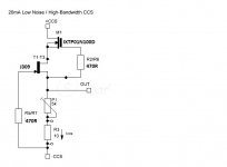
I used Gyrator directly without SSHV2 for 26, I'm not surprised. Crystal clear but without body & bass. It's a lot better SSHV2 + CCS Ixys as upper and sk170bl for lower for 26, for 4p1l same uppwer device and for lower J310 attached pic with J309 because used only for 15mA for 5687.
Attachments
Last edited:
It would seem a step backwards to me to run without the SSHV2 boards as they are going to give a much quieter supply, and a lower impedance. I used the BF862 JFET in the lower position as per Ales recommendation and it performs beautifully. Still have a few things i want to test out with the biasing setup, but so far i am more than happy with how it is performing..similar to Andys comments above, it just sounds more cohesive then the 4P1L ever did.
Last edited:
I'm getting clean deep bass & body without salas, as stated earlier going from CLCLC TO CLC made a large difference in my case, I used sshv2 for a long tine before using Gyrator, Blitz has also mentioned the removal of a choke earlier in this post cleared things up, you can end up filtering the life out of the music, what works for some doesn't necessarily work in every situation.
Salas Supply
I might even try it with Salas (I just about have space in the box lol), as I happen to have a couple lying around from earlier projects, Ale suggested to me that He felt they were unnecessary with His boards, I am a great believer in keeping it as simple as possible, also bearing in mind this is for 2P29L & not 4P1L.
It would seem a step backwards to me to run without the SSHV2 boards as they are going to give a much quieter supply, and a lower impedance. I used the BF862 JFET in the lower position as per Ales recommendation and it performs beautifully. Still have a few things i want to test out with the biasing setup, but so far i am more than happy with how it is performing..similar to Andys comments above, it just sounds more cohesive then the 4P1L ever did.
I might even try it with Salas (I just about have space in the box lol), as I happen to have a couple lying around from earlier projects, Ale suggested to me that He felt they were unnecessary with His boards, I am a great believer in keeping it as simple as possible, also bearing in mind this is for 2P29L & not 4P1L.
Salas Supply
Are you running SSHV2's Andy?
That's pretty much my PSU - low value cap, choke and then 47uF doubled. All caps are polypropylene motor run. I use a separate PSU for the input stage of my 2-stage amp and I like to use a mesh rectifier like AZ1.
Using a separate PSU for the input allows the output PSU to just provide around 140mA (70+70) which is easier on all the components. Sounds nice too, and can be designed for just the voltage needed, e.g. 200v. Plus I may want to use driver tubes with 30mA of current. That's certainly desirable with a 4P1L. I use plate chokes.
Are you running SSHV2's Andy?
How many of you out there are using Salas SSHV2's with Ale Moglia's Gyrator Boards, how many are not using SSHV2's with them?
Valve
What valve are we talking about here?It would seem a step backwards to me to run without the SSHV2 boards as they are going to give a much quieter supply, and a lower impedance. I used the BF862 JFET in the lower position as per Ales recommendation and it performs beautifully. Still have a few things i want to test out with the biasing setup, but so far i am more than happy with how it is performing..similar to Andys comments above, it just sounds more cohesive then the 4P1L ever did.
I've never built a SSHV2. No doubt I should, but I haven't. I used to use glow tubes but haven't for a while. I should probably try one again and listen to the difference. I have plenty. I found that I got audible improvements from a big choke, both in value and size, and a mesh rectifier. I've always used nothing but motor run polypropylenes - never any electrolytics.
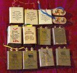
I have some of those big old box shaped grey paper in oil caps and I should take them out and use them. For instance as the last cap in the PSU. Has anyone used these? I have mostly 2uF at 400v.
I have some of those big old box shaped grey paper in oil caps and I should take them out and use them. For instance as the last cap in the PSU. Has anyone used these? I have mostly 2uF at 400v.
Attachments
Caps.
Nice little stash Andy, those Dubilier ones are very good too. My first cap is usually the exotic one & after that they get too expensive, but I'm a big fan of Lundahl chokes & Weiss/Lundahl Transformers.
Nice little stash Andy, those Dubilier ones are very good too. My first cap is usually the exotic one & after that they get too expensive, but I'm a big fan of Lundahl chokes & Weiss/Lundahl Transformers.
You could run the Gyrator, or any CCS plate load without anything in front of it, but having an active regulator is going to perform even better. They way i think of it is anything in front of an active regulator, is for the most part irrelevant as its going to..
-filter out any voltage ripple
-isolate any noise on the power supply
-present a low impedance supply (spec quotes 11mOhm output impedance 20Hz to 20kHz)
-allow you to set an output voltage (i.e. voltage regulation)
I measured the amps frequency response and noise floor with a CRC and CLC supply in front of the SSHV2 and it made no measurable difference whatsoever. I modeled the supply to have less than 1mv ripple going into the regulator, but i belive it could be an order of magnatude higher and not matter.
As with everything there is no free lunch, the downsides are:
-Space issues - finding room in the chassis for one or two boards
-Thermal issues - depending on current demand your going to need to attach to a chassis or dedicated heatsink
-Voltage drop - Spec claims the SSHV2 needs 20v higher supply than output, in reality i have found ~35v is more realistic
-Current needs - the SSHV2 circuit needs to drop ~20ma above the output current. If you are running two boards like i am thats an additonal 40ma of current you need to factor into the raw B+ supply.
I was never a fan of tube based rectifiers, amps always sounded slow and muddy to me. What i would suggest is to try a SiC based rectifier which will bump up your raw B+ by 30-40volts depending on the tubes you were using, then use SSHV2 boards and drop that additonal voltage across them and test it out.
For example my 01A has a 200v B+ into the SSHV2, 150v out into the Gyrator boards, then about 110-120v on the plates. I cant remember the voltages of my 4P1L off hand, was something like 260volts B+ and 150v at the plates.
Nice little stash Andy, those Dubilier ones are very good too. My first cap is usually the exotic one & after that they get too expensive, but I'm a big fan of Lundahl chokes & Weiss/Lundahl Transformers.
I would do it the other way around, if your only going to use one nice film or PIO capacitor i would put it at the end of the supply just before the load.
How many of you out there are using Salas SSHV2's with Ale Moglia's Gyrator Boards, how many are not using SSHV2's with them?
I used both: with SSHV2 & without SSHV2.
Salas Supply
I did originally build a 26 Amp (about 10 years ago) using sshv2, glow tubes ccs with op transformer, it was ok but I was never that happy with it, I often wondered about building using SS Supply, it'll cost very little to utilize as well. Thanks for your input.You could run the Gyrator, or any CCS plate load without anything in front of it, but having an active regulator is going to perform even better. They way i think of it is anything in front of an active regulator, is for the most part irrelevant as its going to..
-filter out any voltage ripple
-isolate any noise on the power supply
-present a low impedance supply (spec quotes 11mOhm output impedance 20Hz to 20kHz)
-allow you to set an output voltage (i.e. voltage regulation)
I measured the amps frequency response and noise floor with a CRC and CLC supply in front of the SSHV2 and it made no measurable difference whatsoever. I modeled the supply to have less than 1mv ripple going into the regulator, but i belive it could be an order of magnatude higher and not matter.
As with everything there is no free lunch, the downsides are:
-Space issues - finding room in the chassis for one or two boards
-Thermal issues - depending on current demand your going to need to attach to a chassis or dedicated heatsink
-Voltage drop - Spec claims the SSHV2 needs 20v higher supply than output, in reality i have found ~35v is more realistic
-Current needs - the SSHV2 circuit needs to drop ~20ma above the output current. If you are running two boards like i am thats an additonal 40ma of current you need to factor into the raw B+ supply.
I was never a fan of tube based rectifiers, amps always sounded slow and muddy to me. What i would suggest is to try a SiC based rectifier which will bump up your raw B+ by 30-40volts depending on the tubes you were using, then use SSHV2 boards and drop that additonal voltage across them and test it out.
For example my 01A has a 200v B+ into the SSHV2, 150v out into the Gyrator boards, then about 110-120v on the plates. I cant remember the voltages of my 4P1L off hand, was something like 260volts B+ and 150v at the plates.
CLC
2 schools of thought there, but it may be irrelevant if I go lclc, as vinylsavor suggests & I know, there'll be a larger voltage drop.I would do it the other way around, if your only going to use one nice film or PIO capacitor i would put it at the end of the supply just before the load.
Just to follow up, I went to LCLC that made everything looser, also voices had less extension on top, not so open, changed back to single 10H choke and voila, then changed to single SSHV2(can't use 2 as Tranny would be close to limit), this tightened things up a little but robbed the top end, this took a lot of life out of the music, but I'm generally pleased with CLC without sshv2, smaller choke improved things quite a lot. Musicality.
preamplifer 4p1l DHT con PCB fai da te
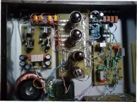
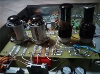
hi I introduce myself for the first time to write on the forum even if I have been reading a bit of everything for 20 years. I am a self-builder of tube pre-amplifiers and I have tried many types of preamps from SRPP to cathode follower etc. always with triodes having satisfaction in the listening tests but perhaps not finding what I wanted; what was present in one type was missing in the other or what a certain triode gave you you could not find in the other, and therefore always surfing the net in search of something different from what I had already realized I was intrigued to the construction of a preamp with the use of PENTODES and precisely with 4P1L and thanks to the information taken from Bartola's site I have created the preamp that I will show in the picture and that I could publish my printed circuits designed by me. I must say that being for the first time dealing with Pentodi I had a bit of difficulty that at the moment I still do not completely solve. I was able to listen to it in an undefined way and I immediately found in the listening an impact of well detached and distinct instruments and a well defined bass with a high volume listening without annoyance ..... I am satisfied
..... BUT WE COME TO THE PROBLEM THAT I STILL HAVE TO SOLVE AND ASK FOR AN OPINION DO YOU HAVE COLLABORATORS
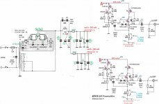
I am using a transformer with secondary output of 220 volts and applied to the 2 rectifier valves 5y3 (I used these because I had them) after the capacitive / inductor / capacitive filter I get 310 volts DC which are doubled with a resistance of 47 hom 3 watts and again filtered with a 2 microfarad polypropylene capacitor per channel and applied to the CCS card I exit the 100 hom resistance with 160 vol. here we are
as soon as I insert [ONE VALVE ONLY the voltage drops to 71 volts. on one channel and the other with a 70 volt valve inserted. This leads to audible background noise without dull and continuous music typical when a transistor or Mos Fet jumps into a power amp
now in my opinion the problem could lie in the 5y3 valves which being each 150 millyamper max output and therefore having a total of 300 mA are few to manage the CCS and the 4P1L and to respect the socket I would like to mount the 5U4G valves or the 5C3S Russian they give me 500 mAmper in total
In your opinion it could be a problem of current absorption and therefore using tubes with higher amperage. I have the problem in the CCS?
thanks to everyone who will give some useful suggestions to others
hi I introduce myself for the first time to write on the forum even if I have been reading a bit of everything for 20 years. I am a self-builder of tube pre-amplifiers and I have tried many types of preamps from SRPP to cathode follower etc. always with triodes having satisfaction in the listening tests but perhaps not finding what I wanted; what was present in one type was missing in the other or what a certain triode gave you you could not find in the other, and therefore always surfing the net in search of something different from what I had already realized I was intrigued to the construction of a preamp with the use of PENTODES and precisely with 4P1L and thanks to the information taken from Bartola's site I have created the preamp that I will show in the picture and that I could publish my printed circuits designed by me. I must say that being for the first time dealing with Pentodi I had a bit of difficulty that at the moment I still do not completely solve. I was able to listen to it in an undefined way and I immediately found in the listening an impact of well detached and distinct instruments and a well defined bass with a high volume listening without annoyance ..... I am satisfied
..... BUT WE COME TO THE PROBLEM THAT I STILL HAVE TO SOLVE AND ASK FOR AN OPINION DO YOU HAVE COLLABORATORS
I am using a transformer with secondary output of 220 volts and applied to the 2 rectifier valves 5y3 (I used these because I had them) after the capacitive / inductor / capacitive filter I get 310 volts DC which are doubled with a resistance of 47 hom 3 watts and again filtered with a 2 microfarad polypropylene capacitor per channel and applied to the CCS card I exit the 100 hom resistance with 160 vol. here we are
as soon as I insert [ONE VALVE ONLY the voltage drops to 71 volts. on one channel and the other with a 70 volt valve inserted. This leads to audible background noise without dull and continuous music typical when a transistor or Mos Fet jumps into a power amp
now in my opinion the problem could lie in the 5y3 valves which being each 150 millyamper max output and therefore having a total of 300 mA are few to manage the CCS and the 4P1L and to respect the socket I would like to mount the 5U4G valves or the 5C3S Russian they give me 500 mAmper in total
In your opinion it could be a problem of current absorption and therefore using tubes with higher amperage. I have the problem in the CCS?
thanks to everyone who will give some useful suggestions to others
Attachments
Hi Andreas,
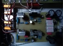
Do you have a diagram of your power supply? I don’t see many “big” capacitors in your pictures.
Regards, Gerrit
Do you have a diagram of your power supply? I don’t see many “big” capacitors in your pictures.
Regards, Gerrit
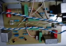
hello gerrit all the components both capacitors and resistors are welded under the valve board from the photo you can see the prolipropylene capacitor in red I am attaching the diagram that follows the original with some variations such as the straightening tubes and the splitting of the voltage. I think the problem lies in the rectifier valves I could try to rectify with diode bridge to see what happens
I repeat with the voltages I find myself and when I go to insert the valves that go down to 70 volts while they should be 145 volts
I repeat with the voltages I find myself and when I go to insert the valves that go down to 70 volts while they should be 145 volts
Attachments
That's one of Ale's gyrators i believe. So is it adjusted correctly for current? And are all the devices in it working? Ale always suggests trying it out with a dummy load first - what does that show you? It should all be on his website, Bartola Valves.
- Home
- Amplifiers
- Tubes / Valves
- 4P1L DHT Line Stage