i think the falling bass with 1.5k have something to do with the output caps..The Tram use min 10uf
i use pt. 4.7uf and do not miss the deep bass,
i use pt. 4.7uf and do not miss the deep bass,
Hi Michael,
As you know, "no free lunch". 🙂
You realized a high pass filter (430nF - 3k5+1k5 resistor) with "enormous" (about 1k5) signal resistance. 😛
If you use (I think unnecessarily) R1 (1k) resistor between CCS and anode, and output is from the anode, output resistance will be about 1k5.
Leave this resistor, and use CCS bias resistor "upper" point as output (low Z output). Output resistance decreases to 200R region.
p.s.
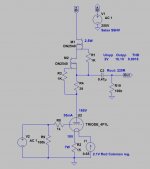
Your CCS schematic is wrong.
As you know, "no free lunch". 🙂
You realized a high pass filter (430nF - 3k5+1k5 resistor) with "enormous" (about 1k5) signal resistance. 😛
If you use (I think unnecessarily) R1 (1k) resistor between CCS and anode, and output is from the anode, output resistance will be about 1k5.
Leave this resistor, and use CCS bias resistor "upper" point as output (low Z output). Output resistance decreases to 200R region.
p.s.
Your CCS schematic is wrong.
Attachments
Hi...
Thanks for your suggestions. Another option would be to
have a switch so I for instance can switch in 3 different resistors.
1.5K absolutely no microphonics.
10K - very nice and very little, but more micro details.
100K - almost as I have before.
@Bjarne.
Truly right with the higher Caps would prevent this.
Don't know if the issue with higher value caps also affect the detail level as It have done I my previous 6922/ECC88 preamp.
I might be another story in a 4P1L, don't know.
Last edited:
Hi Michael,
As you know, "no free lunch". 🙂
You realized a high pass filter (430nF - 3k5+1k5 resistor) with "enormous" (about 1k5) signal resistance. 😛
If you use (I think unnecessarily) R1 (1k) resistor between CCS and anode, and output is from the anode, output resistance will be about 1k5.
Leave this resistor, and use CCS bias resistor "upper" point as output (low Z output). Output resistance decreases to 200R region.
p.s.
Your CCS schematic is wrong.
My CCS was just meant as an illustration. I'm using the gyrator ver 1b.
Which I like a lot.

Hello
just get new caps for the output in 4P1L
Rike Qcaps 0.47uf....replace my mundorf silver in oil
just out of the bag ,the Qcaps sound really good,,,but i think they will get even better when i have 100hours or more on them..
will return with more ,
Best bjarne
just get new caps for the output in 4P1L
Rike Qcaps 0.47uf....replace my mundorf silver in oil
just out of the bag ,the Qcaps sound really good,,,but i think they will get even better when i have 100hours or more on them..
will return with more ,
Best bjarne
Hello
just get new caps for the output in 4P1L
Rike Qcaps 0.47uf....replace my mundorf silver in oil
just out of the bag ,the Qcaps sound really good,,,but i think they will get even better when i have 100hours or more on them..
will return with more ,
Best bjarne
RIKE is a really NICE Cap. I have the "little brother" SCaps and it has lots
of both details and warm.
Give it at least 150 hour, before it settles.
/Regards Michael.
Hi
Due to some regulating issues Bjarne has with on of the posted CCS gyrator ver 1b
I'll release this Schematic for Caps which both works for 8R and 15R.
I'm playing on it right now. It's very very stable on my 8R and the mA is only "drifting" 0.35% when I set it to 30mA.
I can adjust the gyrator from 15.8mA to 40mA. When 30mA is my favourite.
Schematic for 8R Caps.
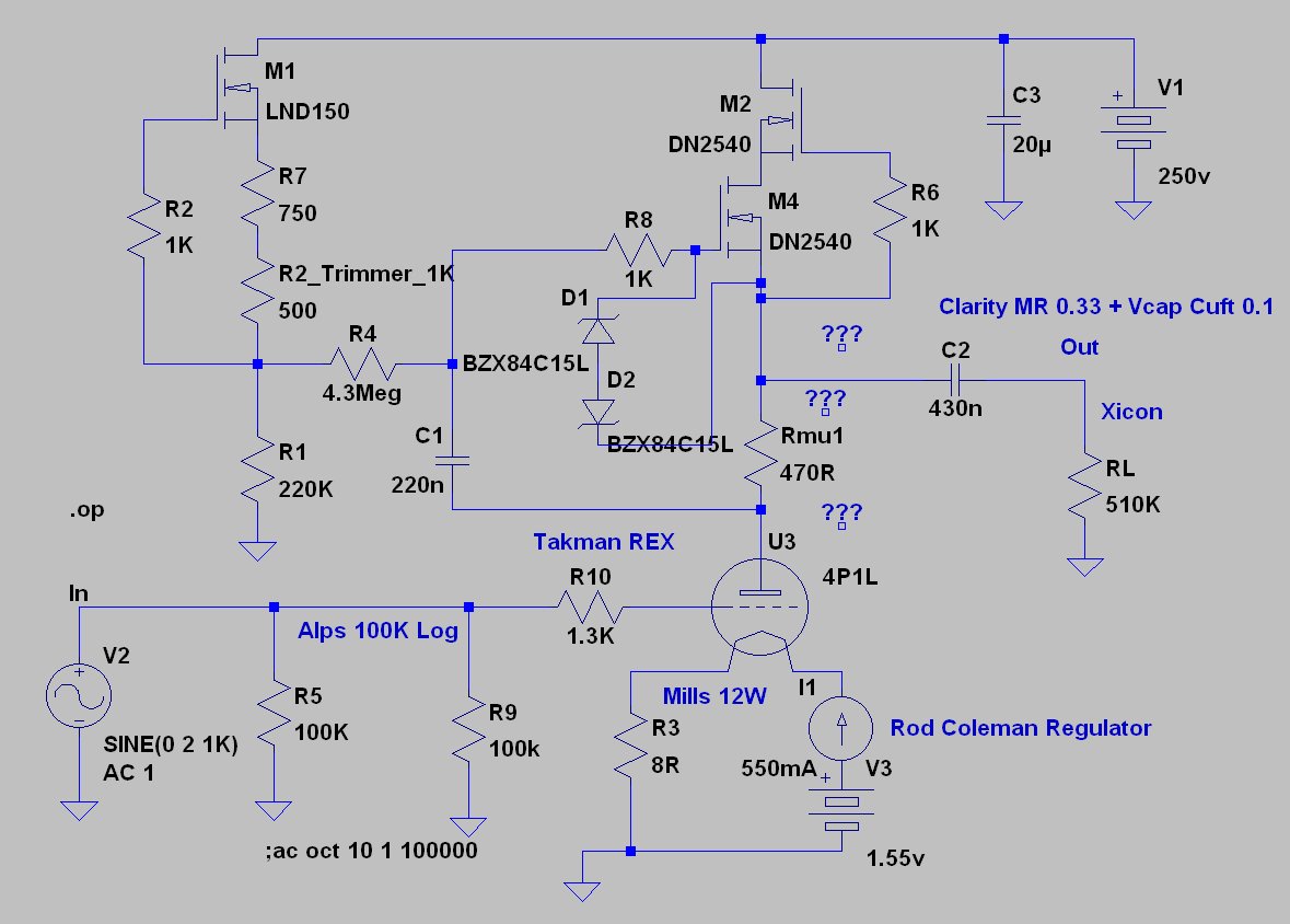
PS! Forget about the voltage Amps on Lt-Spice, it's different in real life.
/Michael.
Due to some regulating issues Bjarne has with on of the posted CCS gyrator ver 1b
I'll release this Schematic for Caps which both works for 8R and 15R.
I'm playing on it right now. It's very very stable on my 8R and the mA is only "drifting" 0.35% when I set it to 30mA.
I can adjust the gyrator from 15.8mA to 40mA. When 30mA is my favourite.
Schematic for 8R Caps.
PS! Forget about the voltage Amps on Lt-Spice, it's different in real life.
/Michael.
Gentlemen, while I use an output transformer, I think you might want to try in this plate load circuit the IXYS IXTP08N50D2 or IXTP08N100D2 MOSFET in place of the DN2540N5. Same pin-out and basic specs, but significantly more open sounding in the usual plate load current source application.
Gentlemen, while I use an output transformer, I think you might want to try in this plate load circuit the IXYS IXTP08N50D2 or IXTP08N100D2 MOSFET in place of the DN2540N5. Same pin-out and basic specs, but significantly more open sounding in the usual plate load current source application.
Hi Kevin...
Will try this on my next mouser order. Thanks for the Tip..
For some years I use (1000V) IXTP01N100D as "upper" FET in the cascode CCSs.
In six months I lost about a handful DN2540 FETs (close to 400V), even though I used protecting zeners. :-(
IMHO "voice" of IXTP FETs is such as Kevin wrote.
Unfortunately I do not have usable 01N100 spice model, therefore in LTSPICE I use DN2540 ones :-(
In six months I lost about a handful DN2540 FETs (close to 400V), even though I used protecting zeners. :-(
IMHO "voice" of IXTP FETs is such as Kevin wrote.
Unfortunately I do not have usable 01N100 spice model, therefore in LTSPICE I use DN2540 ones :-(
Last edited:
I've used the 01N100D for some years in a 46 driver with filament bias into a triode strapped 814 SE amp which sounded beautifully. Sadly the amp is now retired
Is the IXYS 10M45S a better sounding alternative to the DN2540 here? I have some....
Unfortunately no. I also have some, and use its in PSU (as CCS).
IXYS IXTP08N50D2 or IXTP08N100D2 MOSFET in place of the DN2540N5.
Hi Kevin,
And what about Crss?
IXTP08N50 11pF
IXTP08N100 6.5p
DN2540 1-5p
IXTP01N100 2p
Up to 1mA CCS I use LND150 (has only 0.5-1p).
Hi Kevin,
And what about Crss?
IXTP08N50 11pF
IXTP08N100 6.5p
DN2540 1-5p
IXTP01N100 2p
Up to 1mA CCS I use LND150 (has only 0.5-1p).
I don't care so much about the Crss or other such parameters. They obviously have predictive value in certain ways, but my experience with choosing components based on ranking a particular parameter and having a positive sonic outcome as a result of that choice has yielded few strikingly positive correlations. I've come to the conclusion after having done this sort of work for my "day job" over the past 19 years that the most is gained by following my ears. Of course, measurements and parameter considerations play a role, but not a determinative one, usually. However, correlations can be drawn over time between favorable sonic results and particular devices, parameters, etc., but largely as a result of empirical observations.
What about "lower" FET? What do you use in this place? What sounds better?For some years I use (1000V) IXTP01N100D as "upper" FET in the cascode CCSs.
I prefer a jFET as the lower FET to minimise the output capacitance and high-frequency response. The DN2540 and other depletion FETs have a very high capacitance when connected in cascoded as the lower device due to the low VDS in place (see data sheet).
The gyrator with the jFET (e.g. 2SK170 or BF862) sounds much better in my view.
The gyrator with the jFET (e.g. 2SK170 or BF862) sounds much better in my view.
Hi Ale,
(2S)K170 or BF862 is very good choice if you use cascode (CCS or gyrator) only with a few mA current.
If you want to work over 25mA there are only few options as a "lower" FET.
I use -your design- cascode gyrator (DN2540s) with pretty good results.
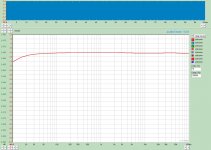
This sample is one of my (graphite anode) 801 measured transfer function (LND150 biased DN2540 cascode gyrator, 1Veff input, 30mA anode current, 400V B+).
Today I was like Cinderella, assorted about two hundred different FETs. 🙂
K117GR: 2.5...6.2mA
K170GR(?) (from various acquisitons): 3...6.2mA. Up to 5.9mA the distribution is uniform, but only four pieces over 6mA. 🙁
J310(OnSemi): 32mA...39mA, mostly about 35mA.
J310 (Siliconix): 29...39mA, mostly about 30mA.
Tomorrow I will try this gyrator configuration with J310 FET as "lower" device.
(2S)K170 or BF862 is very good choice if you use cascode (CCS or gyrator) only with a few mA current.
If you want to work over 25mA there are only few options as a "lower" FET.
I use -your design- cascode gyrator (DN2540s) with pretty good results.
This sample is one of my (graphite anode) 801 measured transfer function (LND150 biased DN2540 cascode gyrator, 1Veff input, 30mA anode current, 400V B+).
Today I was like Cinderella, assorted about two hundred different FETs. 🙂
K117GR: 2.5...6.2mA
K170GR(?) (from various acquisitons): 3...6.2mA. Up to 5.9mA the distribution is uniform, but only four pieces over 6mA. 🙁
J310(OnSemi): 32mA...39mA, mostly about 35mA.
J310 (Siliconix): 29...39mA, mostly about 30mA.
Tomorrow I will try this gyrator configuration with J310 FET as "lower" device.
Attachments
- Home
- Amplifiers
- Tubes / Valves
- 4P1L DHT Line Stage