Raaf61,
I expected you had the voltage there, but . . .
-70V was not listed in the schematic in post # 64.
Some persons build off of the schematics here.
I expected you had the voltage there, but . . .
-70V was not listed in the schematic in post # 64.
Some persons build off of the schematics here.
IMHO 350V AC transformer is a bit "large" for 300V DC output.
My LTSpice simulation shows about 344V output (PSUD is too modest for complex circuits).
Each L-C circuit generates enormous current not only within choke, but in diode.
The rectifier's peek current is about 400mA (at startup the 100uF charging current and the 10H magnetising current sum exceed 1A!), the RMS current about 200mA.
Attachments

You might remove the 100uF, then put one 14.7uf right after the first choke, and put a 50 uF after each 6H choke. Just requires one more 50 uF cap, but it makes the job easier for both the rectifier and the power transformer secondary (less power up current transient, less running ripple current, and less hot when operating). You will have about the same ripple as before. And . . . B+1 and B+2 will not move as much when bass notes come along (rectifier ripple at 100Hz filtering, versus B+ variations with 30, 40, 50Hz organ and bass notes that suck out current over the longer time periods of the low frequencies).
Last edited:
Hello, Using 100uf will indeed give a the choke ,the rectifier and the ttransformer a huge task. If the current through the choke will be to big it will not act like a choke anymore and the rectifier will not work as it is supposed to do. When the choke will not act as a choke the system turns into a capacitor inputduring the short '' time '' when there is a charging pulse i presume and the voltages will be higher. An ordinary meter will of course not show these peaks. That is why i usually go for higher henry chokes which have higher dcr AND reduce the seize of the first capacitor.
Greetings, Eduard
Greetings, Eduard
some info
Hello,
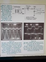
For those not yet convinced that choke input is the way to go.
Extract of an article from Rinaldp Bassi in France.
9A top choke input sine wave 0,6 volts at point B in figure 8
9A bottom no choke saw tooth 5 volts
9B top choke charging current the same as the current being drawn by the circuit.
9B bottom current fluctuating between circuit current ( 180mA) and charging pulses well over 400 mA
Greetings, Eduard
Hello,
For those not yet convinced that choke input is the way to go.
Extract of an article from Rinaldp Bassi in France.
9A top choke input sine wave 0,6 volts at point B in figure 8
9A bottom no choke saw tooth 5 volts
9B top choke charging current the same as the current being drawn by the circuit.
9B bottom current fluctuating between circuit current ( 180mA) and charging pulses well over 400 mA
Greetings, Eduard
Attachments
I have been playing with psud2 and can't get rid of the overshoot and the ringing (on the first C) with a choke input, I do seem to get the start-up current within limits .
I need to read more about psu design and probably learn to work with LT Spice .
The funny thing is the amp sounds nice with this bad designed psu
I need to read more about psu design and probably learn to work with LT Spice .
The funny thing is the amp sounds nice with this bad designed psu
Last edited:
... psud2 ? ... it gives a huge overshoot and voltages are not realistic. ....
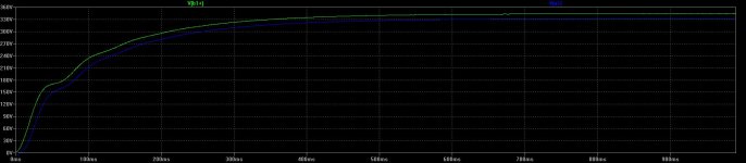
You have started from ZERO time. Yes, an L-C filter tends to overshoot *at turn-on*. This seems to be settled by 0.5 Seconds. How much music can you listen to in a half a second?
Forget the start-up, except to be sure the peak will not blow-up your capacitors. Set "reporting delay" to several seconds. In this case, 1 second gets past the big bump, but it takes like 7 seconds to settle to final value.
Your "350V 182r" transformer is delivering 475V peak, which implies 339Vrms, so you lose some there.
Choke-load "should" make a DC about 0.9X the ACrms, so 304V.
The GZ37 has about 29V drop, steady because of choke-load. So now 275V.
118mA in 60r choke is a 7V drop, down to 268V DC.
PSUD says 260V.... BUT I have to let the sim run 7 seconds to settle-down to final value. Which agrees with bench-test: a big-choke big-cap filter can take visible time to get to its long-term final value. (And in real life tube-warm-up causes several other delays and burbles.)
I am mildly curious why 268V versus 260V, but 3% difference is "nothing" in tube-work where anything +/-20% is all about the same.
Attachments
Hello,
If you have a 400 volt transformer you should try an input choke with more Henry or add anotherLL1673 in series. Then try using smaller caps and higher quality closer to the circuit.
Greetings, Eduard
If you have a 400 volt transformer you should try an input choke with more Henry or add anotherLL1673 in series. Then try using smaller caps and higher quality closer to the circuit.
Greetings, Eduard
I am aware that a 400V transformer and or better chokes / capacitors should give me better performance but I have neither in stock .
Then there's also the budget issue plus the fact that this amp sounds already better than I expected .
So, for the moment I would like to focus on fine-tuning this setup although getting the caps closer to the 45's would be a sensible thing to do .
I like the basics of this psu with mkp, I am trying out different sorts of bypass caps now .
The MKC's have already gone I found I had some old Philips KS (non-metalised polystyrene) in stock and they are really nice performers .
So no tech issues here at the moment, just soldering caps in and listening 😉 .
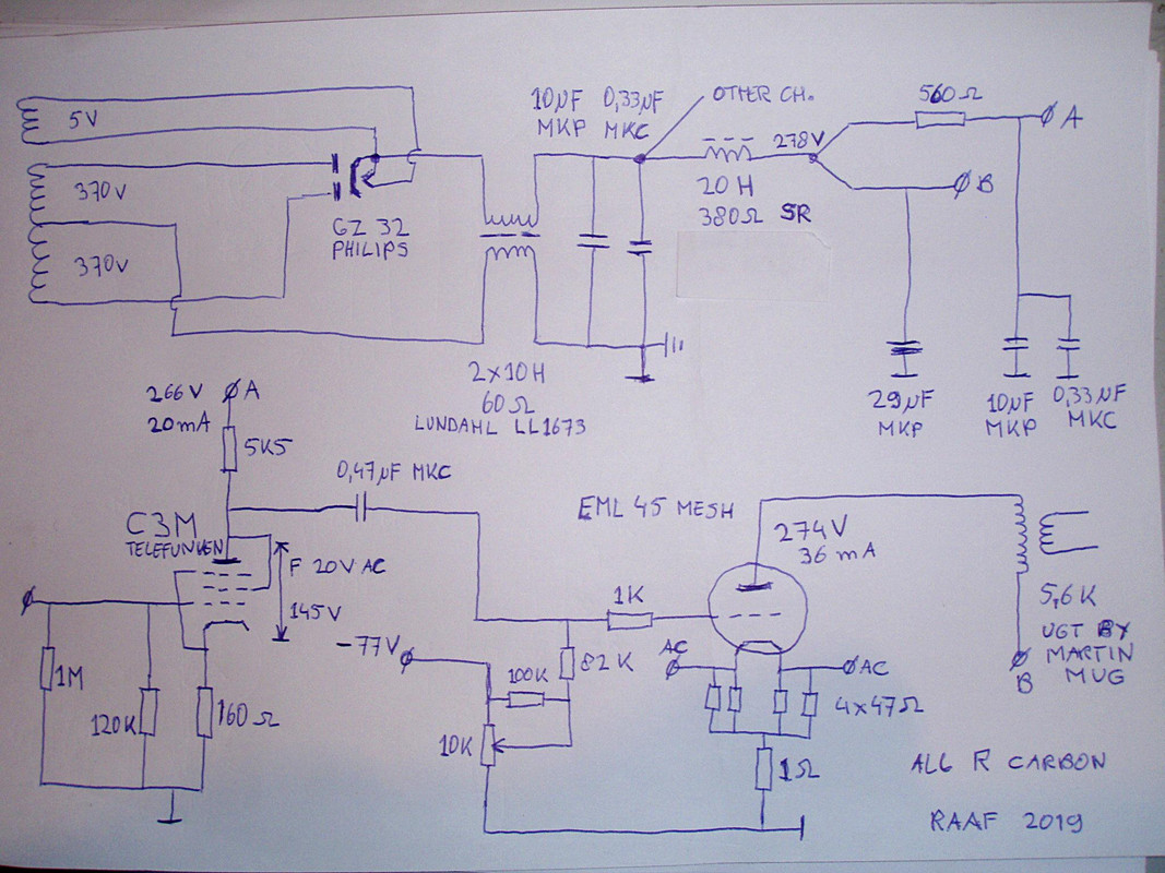
Here's the definitive version, for as far as my amps are ever definitive.
I have found by-pass caps I am truly happy with.
The psu caps are as close as possible to the circuits they supply, the C3M has a different circuit, draws only 6 mA instead of 20 mA but amplifies more, the system does 105dB now.
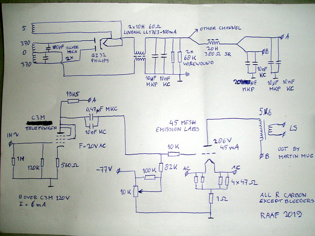
I am aware that a 400v transformer and better chokes should give me better performance so nice to know that a upgrade is possible .
I am happy with this Amp, expected a better performance than my EL3N pushpull but the sonic difference is way more than I hoped for .
Enjoying music has reached another level .
I have found by-pass caps I am truly happy with.
The psu caps are as close as possible to the circuits they supply, the C3M has a different circuit, draws only 6 mA instead of 20 mA but amplifies more, the system does 105dB now.
I am aware that a 400v transformer and better chokes should give me better performance so nice to know that a upgrade is possible .
I am happy with this Amp, expected a better performance than my EL3N pushpull but the sonic difference is way more than I hoped for .
Enjoying music has reached another level .
Hello,
Check the voltage rating of the wire wound bleeder resistors.
They can som,etimes handle a lot of current but can be restricted in voltage and in this position there is a lot of voltage.
Greetings, Eduard
P.s found some film and foil 470nF 1000 volts polypropylene made in the eighties for a nice price. If you install them on a board it will be easy to make nice little capacitor.
I had it checked but just double-checked 😉, the bleeder resistors can handle 500 V .
https://www.vishay.com/docs/21002/g200.pdf
Sorry Eduard but nothing beats the KC (Non-metalised polycarbonate) caps for me .
https://www.vishay.com/docs/21002/g200.pdf
Sorry Eduard but nothing beats the KC (Non-metalised polycarbonate) caps for me .
Last edited:
Capacitors are a discussion unto themselves.
And some who only have one type to try, just say "Curses, Foiled again".
And some who only have one type to try, just say "Curses, Foiled again".
😀
Just use whatever capacitor you like, it's pointless having discussions about taste and or belief .
Just use whatever capacitor you like, it's pointless having discussions about taste and or belief .
Hello,
Only the person buying the caps will usually listen so why should we bother.
I remember buying the 470nF caps ( i mean the same series but some other values) at a price which was expensive in the eighties for diy in a diy audio store which had most of the times surplus parts for sale. At that time i visited the factory close to Paris and the price i paid at the store was cheap said the staff of the manufacturer.
Will take some to Asia later this year.
Greetings, Eduard
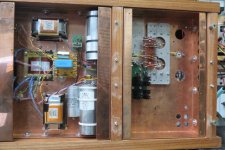
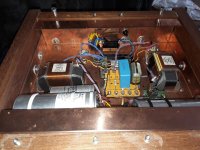
P.s in the attachment my new line preamplifier. Everything mounted so far is power supply. At the far right there is a noval support for the signal tube and two round holes for the Tango output transformer. The empty space in the right part will be occupied by Slagle AVC
Only the person buying the caps will usually listen so why should we bother.
I remember buying the 470nF caps ( i mean the same series but some other values) at a price which was expensive in the eighties for diy in a diy audio store which had most of the times surplus parts for sale. At that time i visited the factory close to Paris and the price i paid at the store was cheap said the staff of the manufacturer.
Will take some to Asia later this year.
Greetings, Eduard
P.s in the attachment my new line preamplifier. Everything mounted so far is power supply. At the far right there is a noval support for the signal tube and two round holes for the Tango output transformer. The empty space in the right part will be occupied by Slagle AVC
Attachments

Hello,
Just did order a pair of LL2771 1A 3H or 2A 700mH for a friends Hiraga power amp.
And a LL2771 6 Henry 500mA and a special request for me 15H 200 mA for some circuits in my DDDAC.
I am going to build a VT25A DRD ''power '' amplifier because i ALWAYS use choke input and tube rectifiers i have been thinking about a 100mA LL2771 choke which will be around 30 Henry but just a total DCR of 11,2 ohm. It is big but apart from that any disadvantages of using this choke for a choke input??
Greetings, Eduard
Mind the impedance of your power supply Eduard. One can check its behaviour by setting a Step Load in PSU-designer and devide the difference (delta E over delta I). You do not want a marginally stable power supply. Long time ago I ended up with a supply that exaggerated 25Hz and could not beleave what was happening to the low notes in the music. That was a funny afternoon listening to familiar music 🙂
- Home
- Amplifiers
- Tubes / Valves
- 45 SE amp