Hello,
Even after a choke input the total value of your capacitor seems a bit high to me.
You can try to create a centre tap at the 5 volt rectifier connection.
There are some Shizuki metalized polypropylene in oil available in the UK.
Greetings, Eduard
Even after a choke input the total value of your capacitor seems a bit high to me.
You can try to create a centre tap at the 5 volt rectifier connection.
There are some Shizuki metalized polypropylene in oil available in the UK.
Greetings, Eduard
The pio's are swapped for ERO mkc and the sparkle is back.
Then took out 44uF capacity and the depth comes back . (I have to fine-tune this)
Logic step because I improved the filtering by connecting the first double choke right so I have to compensate this to get the sound back I had before the correction .
@ eduard :
What do you mean with creating a centre tap, with capacitors ?
eduard,
Are you suggesting to create a center tap on the rectifier tube 5VAC winding? With Capacitors?
5V windings are either center tapped or they are not.
If you have a 350V-0-350VAC HV secondary, But No center tap on the rectifier 5V winding, It is not the end of the world. Just connect one end of the rectifier 5V filament to the filter choke (always the cathode end of the rectifier filament if it is an indirectly heated rectifier). Suppose the rectifier has a 50V drop, plate to filament. 350VAC = ~ 500Vpeak The voltage on one alternation will be 500 -50 +5 = 455peak, and the voltage on the other alternation will be 500 -50 +0 = 450V peak. Yes, that will give a little ripple voltage at line frequency (50 or 60Hz). But the much bigger ripple voltage will be at 2X the line frequency (100 or 120Hz). Our ears are more sensitive to the higher (2X) ripple frequency.
Filtering 5V ripple at 50 / 60Hz, is easier than filtering 450V to ~ 300V ripple at 100 / 120Hz (the ripple is from the 450V peak, to the B+'s DC level. That ripple is large: ~ 150V. If the choke and following capacitors are any good, that 5V difference at line frequency will be very well taken care of; much easier than the very large ripple at 2X line frequency (if not, fix the filter values).
Last edited:
Low noise is a good thing, right?
I prefer AC glow over DC , I had my amp connected to a isolating transformer and didn't like the clean "dead" sound .....
Hello,
You can put two 50/100 ohm resistors in series and put connect them them between the 5 volt on the transformer. The high voltage output will start at the centre of the two resistors. It is an old trick.
Paper in oil or no paper in oil?? Maybe try metalized polypropylene in oil like the Siemens/Epcos mkv. Or the expensive CSI . Once i did try one from a syurplus store. Very nice but also BIG.
Moving the last cap closer to the circuit could be an improvement too.
AND keeping the connections between rectifier, transformer and input choke and first cap SHORT. The lundahl doesnt radiate a lot of pollution. Of course the two chokes that seperates the two channels could be improved too.
Greetings, eduard
I took out another 20uF capacity and the "magic" is back 😀
Then I pushed the C3M a bit more, they're doing 3,7 watts now (was 3), still in triode with g3 to cathode and that improved dynamics.
Happy with this performance so far .
@ eduard
The first 100uF capacitor is a ASC polypropylene in wax.
the rest are Vishay and Wima mkp "topped off" with ERO mkc (metallised polycarbonate) which I also use for coupling .
I assume I can improve the two old SR chokes but I like to take a short listening break for now .
Last edited:
eduard,
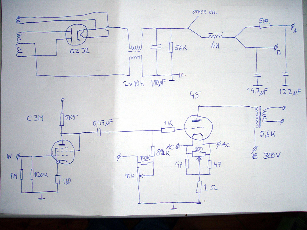
Hello, I believe the rectifier that Raaf61 is using is a GZ32. The GZ32 is indirectly heated, with cathode. Pin 8 is both the filament and cathode connection on the GZ32. Connect Pin 8 (filament and cathode) to the B+ filter, and all is well. You do not want to use a center tapped 5V on a GZ32.
Hello, I believe the rectifier that Raaf61 is using is a GZ32. The GZ32 is indirectly heated, with cathode. Pin 8 is both the filament and cathode connection on the GZ32. Connect Pin 8 (filament and cathode) to the B+ filter, and all is well. You do not want to use a center tapped 5V on a GZ32.
Last edited:
Hello , The drawing of raaf1961 showed a directly heated rectifier with 4 connections on the tube socket. An indirectly heated one will have 5 connections on the tube.
@Raaf1961 Maybe an LCLC with more Henry and less microfarad will give you what you want. I think the Lundahl chokes add their own sound to the supply than a mix of caps. ASC is also oil no wax.But it is no paper but plastic. Maybe you could try the Obbligato. If the input tube takes a little current you could try a small choke. With the 5k5 on the input tube you can also change the sound so to say. Try a Mills there!! Greetings, Eduard P.s i have some 9Henry 15 mA chokes
@Raaf1961 Maybe an LCLC with more Henry and less microfarad will give you what you want. I think the Lundahl chokes add their own sound to the supply than a mix of caps. ASC is also oil no wax.But it is no paper but plastic. Maybe you could try the Obbligato. If the input tube takes a little current you could try a small choke. With the 5k5 on the input tube you can also change the sound so to say. Try a Mills there!! Greetings, Eduard P.s i have some 9Henry 15 mA chokes
eduard,
Hello, Look at the link for the GZ32: https://frank.pocnet.net/sheets/020/g/GZ32.pdf Regardless of the number of pins on the socket, there are only 4 connections to the tube. Filament; Plate; Plate; and Filament + Cathode.
Hello, Look at the link for the GZ32: https://frank.pocnet.net/sheets/020/g/GZ32.pdf Regardless of the number of pins on the socket, there are only 4 connections to the tube. Filament; Plate; Plate; and Filament + Cathode.
Hello,
Ok we will focus on improving the actual components being used. I truly believe that a good choke is much easier to apply than a capacitor. Adding a good quality second choke could give you the opportunity to use smaller caps which will be an advantage.
I am a big fan of oil caps. Paper in oil could add some signature to the sound but i like it. There are still caps filled with oil manufactured but not using paper but some kind of foil.
I found some on ebay. I will stock up because there are some that work and some that you would expect to work but they dont.
Greetings, eduard
I prefer AC glow over DC , I had my amp connected to a isolating transformer and didn't like the clean "dead" sound .....
I wish I knew what the OP:s preference for AC heating and his dislike of isolation transformers has to do with the configuration of the power supply.
Hello, It is not always clear what people are looking for in audio. Just piling up different lots of different caps could give an unbalanced sound. I remermber a few years back someone was using a lundahl choke in a dddac and it was wired wrong. But he had some theory why his way of connecting was the perfect one. In fact he did cancel the choke effect completely . Same like the original poster did in the beginning but he just made a mistake. Nopw it is wired the right way. My idea is to use more Henry and smaller caps. I also think that using MKP just because it is not not an electrolytic capacitor is not always the right choice. I heard a lot of mkp caps that sounded very mediocre. In my loudspeaker filter i tried a lot of them. Had some very high tech capacitors , high voltage so BIG bought in a surplus store but the sound was not like music. Had some audiophile caps bad as well. The two best ones were General Electric dielectrol ( some plastic foil in oil) and Philips paper? in oil. One euro a piece!!! We have to wait for the OP to reappear.
Greetings, eduard
Greetings, eduard
It was a reaction to your remark (I'll quote again) "Low noise is a good thing, right?" I meant to say that this is not always preferable for meI wish I knew what the OP:s preference for AC heating and his dislike of isolation transformers has to do with the configuration of the power supply.
Perhaps my reaction should have been :
Quote: Originally Posted boli46

Low noise is a good thing, right?
This is not always preferable for me, e.g. I prefer AC glow over DC , I had my amp connected to a isolating transformer and didn't like the clean "dead" sound .....
@ eduard
I'll post a updated diagram tomorrow. What am I looking for in audio ?I'm a music lover and because the "hifi shop" could never offer me anything truly satisfying (and affordable) that's why I started building my own stuff . I like a pure system with as little components as possible
And does the name Henri van der Heide say anything ? if not (sorry Netherlands language only) :
DHTRob - Henri van der Heide: Geluid dat niet mag?
Hello,
I am not sure if the GZ32 will like the big cap after the choke. Your choke has low DCR just 60 ohm total.
I just finished a power supply for a friend in Hongkong with the 80 rectifier. Input choke LL2743 41 henry total dcr 400 ohm. First cap 2 mf then 25 henry 170 ohm then 25 mf
The bleeder should be lower in value. If there is 310 volt on the first cap you will need 310 divided by 20H is 15,5 mA.
OK I have two questions :
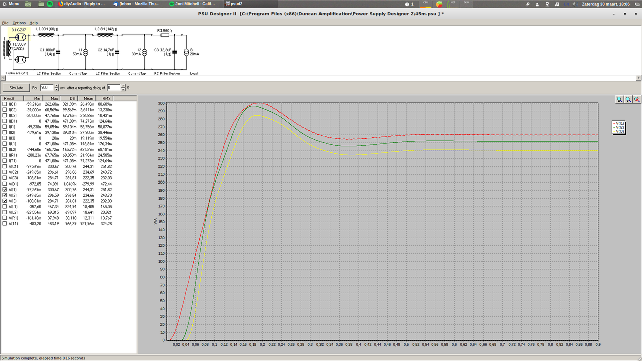
- How can I simulate this psu in psud2 ? I have tried to simulate the psu it gives a huge overshoot and voltages are not realistic .
- If I make the dcr of the first choke 260 ohms (in psud2) things look a lot better. Can I just add 2 100R resistors after the choke to get the same effect ?
Hello,
See what happens if you '' use '' the LL2743 which has total 41 Henry and two times 200Ohm dcr and reduce the seize of the first cap.
Greetings, Eduard
P.s now looking for other caps on ebay
See what happens if you '' use '' the LL2743 which has total 41 Henry and two times 200Ohm dcr and reduce the seize of the first cap.
Greetings, Eduard
P.s now looking for other caps on ebay
If I don't change the cap things look better, but it looks bad if I take 50uF.
But a 20v drop is not acceptable for me
But a 20v drop is not acceptable for me
Last edited:
Solid state rectifiers do have a quick B+ startup. So . . . A diode from the 300B (or 45) grid (anode end of the diode), to one end of the 300B (or 45) filament (cathode of the diode) will prevent the grid from going more than 0.6V positive when the "quick" B+ comes up.
Just my opinion.
nice simple trick this protect the grid from coupling caps charge at start up?
- Home
- Amplifiers
- Tubes / Valves
- 45 SE amp