To reiterate what Jean-Paul said: any surplus capacitor of this type should be checked before use, because most of them come from scheduled equipment maintence and are in a degraded condition, although they look fine visually. This is also true for big film capacitors for industrial applications. ESR is higher than normal and capacity is lower, they may even become slightly warm during use due to the internal losses. They are still usable, but reliability is questionable at this point. Fun fact: I once witnessed a careless and unprepared electrician "checking" if the capacitor bank was discharged by shorting the terminals with the screwdriver. The capacitor should have been discharged at that point, and I guess that the guy had done this many times before without any issues. For some reason, this time it wasen't. That guy will never try again to discharge a capacitor bank with the screwdriver. Capacitor terminals and screwdriver tip vanished in the plasma explosion, and the guy was lucky to only get minimal burns from the stunt.
This thread is nowhere near 200 replies, so how can 99.5 % ignore something? Or do you mean in general, not specifically in this thread?Not dissing anybody, just thinking aloud:
* everybody does the RMS to peak conversion right
* most miss that diode drop is 1V or more at high currents, never generally assumed 0.7V
* almost all (99.5%?) completely ignore transformer DCR.
Which is worsened by charging current being made out of very narrow very high current peaks.
Oh well.
I think Jean-Paul and I covered most of the things you mention.
I mean in general, of course.This thread is nowhere near 200 replies, so how can 99.5 % ignore something? Or do you mean in general, not specifically in this thread?
I think Jean-Paul and I covered most of the things you mention.
The 99.5% reference was clear enough, wasn´t it?
This particular thread mentioned it, one post, but that´s not the average, AT ALL.
Maybe you never heard the British Idiom?:
https://idioms.thefreedictionary.com/one+swallow+does+not+make+a+summer
Also somewhat worried that you ignored my caveat at the very beginning of my post:
and took it personally? 😱Not dissing anybody, just thinking aloud
Not sure why 🙁
It's also Dutch idiom, although in Dutch, there is not much of a distinction between swifts (gierzwaluwen) and swallows (zwaluwen). The swifts should be here again shortly, by the way.
I was under the impression your comment was about this thread, hence I didn't understand it. It's clear now.
I was under the impression your comment was about this thread, hence I didn't understand it. It's clear now.

The more common factory spec on transformers is at full load. Which is what we want here. And probably Gno knows this.completely ignore transformer DCR.
The ripple-depth is often overlooked.
Hey guys.
I just got a bunch, 30 pieces of so, of these really BIG capacitors, only because it was for sale at a very low price.
Now... Is there any use for such big caps in tube amps, or should I just try and resell them to buy other more useful parts?
Seems too big for tube amps for me. Most of what I see use 100 or 220uF high voltage caps, 470uF at most.
And just out of curiosity... What are those big 450v caps used for? Heavy industrial equipment, maybe? What else?
So... Should I just sell them for a burn price online, and buy me more tubes and transformers, or should I keep and use them on tube amps?
What you guys think?
Thanks on advance for any light on this subject!
Those are ok, but not as big as these...
Attachments

That isn't true. I have made and used more than one power supply like that, and so have many others.Yes a 6.3V transformer will never work out with a 7805
When lightly loaded, most of the "6.3V" transformers I've used put out more than 9V DC after rectification and filtering. All you have to do is pick one that will still put out roughly 8 or more volts at the full load current you intend.
No, I did not make a mistake - this is an APPROXIMATE calculation. EVERYTHING about this calculation has substantial inaccuracies, including the starting assumption that the filtered waveform is a sawtooth (it's close to a sawtooth, but it is not a sawtooth).and Gnobuddy makes a mistake with the rectifier diodes dropout.
Some common sense on the part of the reader is necessary. This is electronics we're talking about. Electrolytic caps used to have +100%/-50% tolerance. What is the point of calculating voltage drops of 100 mV in a rectifier diode when the capacitor might actually have half its rated capacitance, and the transformer might put out 15% more voltage than it's rated for? (For example, the last "48 volt" transformer I used spit out 75 volts DC at the filter cap after bridge rectification.)
For a calculation like the one I did in this thread, complaining that transformer internal resistance and accurate diode drop to within ten millivolts haven't been used, is a lot like complaining that someone hasn't calculated the number of cats that will fit in a cubic metre to three decimal places of accuracy.
I disagree. Even if you had an infinite-size heatsink, the 7805's own internal thermal resistance would limit output current to less than 1 amp if you fed it 12 volts DC, which is what you'd get from most 9V transformers. I usually saw over 13.5 volts peak from lightly loaded "9V" transformers.Besides that no one cared about power loss/heat then.
And bigger heatsinks cost more, then as now. The bigger enclosure needed for the bigger heatsink also cost more, and took up more room.
Exactly. And sometimes, it's even worse than that: some rules of thumb were never correct to start with.The problem with reminding rules of thumb is that they often get taken out of context.
Quite incorrect. Transformer winders usually design for rated voltage at full current draw, and most 6.3V AC RMS transformers I've used would spit out 9V DC at the filter cap when lightly loaded, which is just about perfect for a 7805 chip.The 6.3V transformer /7805 combo will never work
-Gnobuddy
Why do caps have such a wide tolerance listed? Even really old ones I’ve measured have been pretty close to their ratings. Everything from 60s era electrolytics to 80s era oil caps.
Electrolytic caps were sort of a desperate-measures technology: the only way that we knew how to make large-value capacitors, but rather a poor and imprecise way, resulting in capacitors with many flaws - but the only game in town, and so still in use, for many decades now.Why do caps have such a wide tolerance listed?
The problem is simply one of numbers. To make a capacitor, you need two or more conducting plates, very closely spaced. It was possible to produce tiny capacitors (a few hundred pico farads) with fist-sized capacitors and plates carefully air-gapped, but for bigger capacitance values, you need larger plates (area), and less distance between them, which is more easily done with a thin film of some sort of insulating material sandwiched between conducting metal foil or something similar.
The film in between has an electrical property called a dielectric constant, which gives you more capacitance for the same plate area and spacing. Some materials (ceramics,for instance) are much better than others (paper, for instance).
With thin ceramic disc dielectrics and reasonably sized "plates" (daubs of conducting paint), it was possible to make capacitors up into the nano-farad range, eventually up into the few-hundred-nanofarads range.
But even this wonder dielectric wasn't enough to get you deep into the microfarads - it takes a thousand nanofarads to make one microfarad, and a thousand-times-bigger capacitor was impractical.
Someone had the brilliant idea to use thinly oxidized aluminium sheet as one electrode. Aluminium oxide is an insulator, and it can be very, very thin, increasing capacitance. But how to make the second electrode maintain close contact over the entire surface of a very thin oxidized Al foil, which is inevitably not quite perfectly flat? The solution was to make the second electrode a liquid, simply rolling up the Al foil and sticking it into the bath of liquid, which would be the second electrode.
The very thin aluminium oxide (Al2O3) layer as dielectric allowed much bigger capacitance values. But what could be done about plate area? How could you get hundreds of times more plate area into the same-size package?
Someone had another brilliant area: etch the plate before oxidizing its surface. The etching process would eat millions of irregular pits into the surface, vastly multiplying the actual surface area (just like the millions of tiny jaggies in a coastline make it much longer). A liquid electrolyte would, of course, be able to flow into all the peaks and dips and pits, making contact with the very thin oxide layer, now spread over a much bigger surface area due to the etching.
So that's essentially how aluminium electrolytic caps are made.
Unfortunately, both the etching/pitting process, and the oxidizing process (to make the dielectric layer), were subject to rather poor manufacturing tolerances. As you can imagine, if the etching went on a little longer or was stopped a little sooner, or the metal happened to be slightly purer and more reactive, or had a rougher or smoother surface finish to start with, one might end up with a considerably different finished area after all the millions of tiny pits had been etched. And that would directly affect the resulting capacitance.
So we got big-value caps, relatively speaking (tens or hundreds of micro farads), but at a price: they had many weaknesses, including poor tolerance, rather poor life (the liquid electrolyte would eventually dry up), poor high-frequency performance (due to the inductance of the coiled-up foil, as well as relatively slow movement of current-carrying ions in the liquid electrolyte), poor heat tolerance (electrolyte would dry out even sooner). Electrolytic caps also "leak" a little DC current - the ultra-thin oxide layer isn't entirely able to stop all DC current flow.
In just the last few years, tiny, low-voltage, multi-layer ceramic caps have become available in sizes up to 22uF and beyond. They are available as through-hole parts as well as SMD. I use the through-hole versions for things like (tube) guitar amplifier cathode bypass capacitors - a 10uF ceramic cap is better in most ways than an old-school 10uF aluminium electrolytic cap, and will probably still be working properly long after I'm dead, unlike electrolytic caps which dry out and fail.
If you measure a bunch of 5% tolerance resistors, you will find most of them are within much less than 5% of their nominal values.Even really old ones I’ve measured have been pretty close to their ratings. Everything from 60s era electrolytics to 80s era oil caps.
This is simply a matter of statistics: in order to make sure worst-case resistors are within 5%, manufacturing tolerances have to be tightened up to the point where most resistors are much more accurate than that. Think of the bell-curve distribution...if the tails are out at +/- 5%, most of the bulk is in the big peak centered around the mean value.
Same thing for caps, of course. In order to avoid having to discard too many on the assembly line, tolerances were typically set at -50% / +100%. But most caps would end up more accurate than that, at least when new. (All bets are off once the electrolyte starts to dry out.)
-Gnobuddy
Now multiply it by 0.9 to handle mains tolerances, subtract 2 V for the rectifier bridge, subtract 1 V or so for ripple and see if you are still above the 7 V it needs to maintain regulation (in case of an L7805C, I vaguely remember other brands need 7.3 V). Then you know if it will work with an ideal transformer.6.3*1.414=8.9... Plenty of drop out room for a 7805.
For a practical transformer, you also have to account for the ratio between unloaded and loaded voltage and the voltage drop across the wire resistance. That makes it better with an oversized transformer and worse with a non-oversized one.
By the way, I never heard of +100 % / -50 % tolerance electrolytic capacitors. It used to be +100 % / -20 % or +50 % / -10 %, or the last couple of decades +/- 20 %.
The output voltage of the L7805C is guaranteed over a 7 V to 20 V input voltage range at junction temperatures up to 125 degrees Celsius and at up to 15 W dissipation. The junction-to-case thermal resistance is 3 K/W max. for the TO-220 version. Hence, at 20 V, you have only 0.6666... K/W left for case-to-heatsink and heatsink-to-ambient if you want to draw 1 A at 70 degrees C ambient temperature (neglecting the effect of quiescent current and output voltage tolerances on the dissipation).
The output voltage of the L7805C is guaranteed over a 7 V to 20 V input voltage range at junction temperatures up to 125 degrees Celsius and at up to 15 W dissipation. The junction-to-case thermal resistance is 3 K/W max. for the TO-220 version. Hence, at 20 V, you have only 0.6666... K/W left for case-to-heatsink and heatsink-to-ambient if you want to draw 1 A at 70 degrees C ambient temperature (neglecting the effect of quiescent current and output voltage tolerances on the dissipation).
Last edited:
Well if I'm honest, I'd use 12VCT, and FW rectifier so only one diode drop. MBR6045 will drop under 0.4V. 10,000µF cap input. Still plenty for the 7805 I think considering the smallest xfmr I can easily find is 25VA.
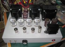
And that power trafo isn‘t exactly peanut sized - I think it can handle the high(er) harmonic current of oversized caps. How high a B+ are you running those? My guess is 400 to 420, with an 8 or 6.6k load, maybe 5k if you’re trying to push them beyond the vertical amp Pdiss rating. But that means more distortion so I’m guessing you’re using the higher Z. Not exactly a huuuuge amp. 30 watts-ish per channel? Over sizing caps won’t cause as many problems at sane power levels as it does when you’re trying to see if you can melt glass.
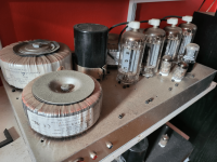
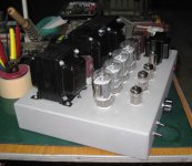
160W power toroids for output? How much power are you getting from them?My setup on a monobloc with 3300µF/450V (Surplus for 6$CAD so why not?)
Dusty McGee, I know but it's relentless here with them build two different condos at once.
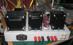
Not necessarily 160 watts output - calculate based on secondary voltage into the load Z. The applied primary voltage won’t be more than the design voltage of 120/240 or you risk the primary inductance going nonlinear enough to notice. A 2x9 V secondary will give 40 clean watts at 8 ohms and 50 Hz- keeping the flux density at what it was DESIGNED for. I doubt you could get any 4X unless you cut out the bass. It doesn’t look like this was one where he stacked two of them.
I understand, hence my question. Those are standard power transformers, plenty of iron for 160VA, I'm interested how much low can they get on the frequency scale before saturation, as well as parasitic capacitance for the top. The 6P45S should do well, plenty of current to spare.Not necessarily 160 watts output - calculate based on secondary voltage into the load Z. The applied primary voltage won’t be more than the design voltage of 120/240 or you risk the primary inductance going nonlinear enough to notice. A 2x9 V secondary will give 40 clean watts at 8 ohms and 50 Hz- keeping the flux density at what it was DESIGNED for. I doubt you could get any 4X unless you cut out the bass. It doesn’t look like this was one where he stacked two of them.
- Home
- Amplifiers
- Tubes / Valves
- 4100uF/450v *BIG* capacitors... any use?