Yeah. Wow, indeed. 4100uF, 450V? Those will hold a scary (as in: lethal) amount of electric charge. Four hundred and fifteen joules per capacitor, when charged to the full 450 volts. 😱Biggest i've come across were the 2000 uF beer cans on the Paoli 60M. Yours dwarf those, though. Wow.
-Gnobuddy
Of course; but (I don't read French) some English translations are still protected.All Jules Verne books are out of copyright
Occurs to me that Verne must be the most-read French literature in English-speaking lands. People do read Proust, Hugo, and Zola (or see them on stage (a friend worked all Broadway showings of Les Misérables)), but not like they read Verne.
I'm at the part now where the capsule is approaching the Moon, past the null-gravity line, and they expect it to flip over "because the center of gravity is low". What is the sound of a one-force couple? It looks like it actually (and conveniently) turns to the attitude which makes the best viewing, because they sure talk a LOT about the view and various theories.
More conveniently, when they pass to the back side of the Moon, it is also the dark side of the Moon. So Jules spared himself a lot of speculation.
Usefull caps if a bit overkill and you'd need a hefty transformer to charge them. Roughly speaking a 100w valve amp needs about 1A at full whack ( a bit less but some headroom is nice for LF transients). According to what I've read you need about 1000u per 1A, therefore a 4100u cap would be good for a 400w valve amp, using say 10 807's in parallel or a lesser number of KT88's. That's with a HT of 450v, for higher HT/B+ use four ( 2 x 2 in series for a CLC/CRC filter) in a 200w amp perhaps.
This is all bag of a fag packet rough calculations, and again as mentioned you'd need a mains tfmr that can supply the current else you get big ripple current.
Andy.
This is all bag of a fag packet rough calculations, and again as mentioned you'd need a mains tfmr that can supply the current else you get big ripple current.
Andy.
I have seen similar stuff used in BIG industrial UPS or "battery backup" systems for the "holdup capacitor" to carry the load for the brief time it takes for the switchover from line power to battery power, as big relays (line contactors) were used then. I also got to see the destruction caused when one of these caps decides to internally short when it's in a bank of about 10 caps, which are fed by a bank of 12 volt lead acid batteries in series. This was an old early 70's vintage UPS that was powering two HP ATE systems in the Motorola radio factory. After the big bang, the old UPS got replaced with something smaller and less scary. Some newer industrial UPS systems rated for low loss use about 400 volts internally.And just out of curiosity... What are those big 450v caps used for? Heavy industrial equipment, maybe? What else?
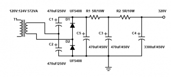
It really needs to be CLC or CRC filter (with the big on at the output like Koda’s). Way too big to be the first cap unless you’re load current is much higher with a very big (1.5 to 2 kVA) trafo. The proper value for a solid state amp is 20,000 uF. What goes into that number? It’s for a 4 Hz corner frequency (5 time constants at 20 Hz) at 2 ohms (Two channels at 4 ohms driven off a common power supply). The resulting conduction angle gives about 60% power factor. Tube amps really aren‘t any different - the LOAD impedance is higher. 1/4 of Ra-a, divided by the number of channels, plus some overhead. That’s how big the first cap should be. Turns out 100 to 500 uF is plenty - even for a big amp. If that’s the only cap, you could go a little larger but certainly not more than about 2X. Anode+g2 current is strictly limited and can’t just scale up by halving or quartering the load Z like a transistor amp can. Additional filtering can be used if you want to drop the ripple, but needs LC or RC to increase the conduction angle or the power trafo won’t really like it. You will get BETTER regulation with the first cap in the right range because it keeps the conduction angle from getting insanely short if you’re drawing high current. Low conduction angle is par for the course if a class AB amp is idling but it’s not trying to pull full current off the trafo either. If you are running class A with constant high load you REALLY don’t want to push the power factor below about 60% unless you like very hot transformers. Which means use CLC (or just LC) filtering if you design for very low ripple on the B+.
Yes, the normal application for those caps would be SOMETHING that uses directly rectified 208 to 277 volt AC. Any transformer would be on the other side of some switching transistors. If it were sized properly (10 ohms load) and being run off rectified 240, there would be about 34 amps (at max loading) of DC current. My guess is the ripple current RATING of that cap would be in the neighborhood of 22 amps. That’s a big power supply, capable of running a 5 horse BLDC motor (modern 20+ SEER AC compressor for example) or multi-kW PA amp. If PFC is used in the DC supply, that improves the power factor and drops the ripple current, even if the cap is “oversized” so a larger cap doesnt cause the issues it would with a conventional audio amp type power supply.
Yes, the normal application for those caps would be SOMETHING that uses directly rectified 208 to 277 volt AC. Any transformer would be on the other side of some switching transistors. If it were sized properly (10 ohms load) and being run off rectified 240, there would be about 34 amps (at max loading) of DC current. My guess is the ripple current RATING of that cap would be in the neighborhood of 22 amps. That’s a big power supply, capable of running a 5 horse BLDC motor (modern 20+ SEER AC compressor for example) or multi-kW PA amp. If PFC is used in the DC supply, that improves the power factor and drops the ripple current, even if the cap is “oversized” so a larger cap doesnt cause the issues it would with a conventional audio amp type power supply.
Of course; but (I don't read French) some English translations are still protected. ...
I'm not convinced that technology is not suitable to launch a space capsule.“Suffer me to finish," he calmly continued. "I have looked at the question in all its bearings, I have resolutely attacked it, and by incontrovertible calculations I find that a projectile endowed with an initial velocity of 12,000 yards per second, and aimed at the moon, must necessarily reach it. I have the honor, my brave colleagues, to propose a trial of this little experiment.”
― Jules Verne
12,000 yards per second is 36,000 feet per second and Google tells me this is 24,545mph ...
Firstly the 'gun' could be very long, say 2km up the side of a mountain, so that is not 100g acceleration.
Secondly, the capsule could still carry a propulsion system, like those shuttles they test launched of 747's.
Cannon to space was built. https://en.wikipedia.org/wiki/Space_gunI'm not convinced that technology is not suitable to launch a space capsule.
Even the underwater form (to avoid great height) will kill most life and instruments. The article says a 37 mile barrel needs 100G to escape the earth. The ocean only goes like 5 miles. The Kola hole went almost 8 miles. https://en.wikipedia.org/wiki/Kola_Superdeep_Borehole
Yes, added boost.... but this was written in 1865. It apparently would not work with gunpowder. Verne (his advisers) grabbed the new guncotton, said to be 5X the power. (And very wicked stuff at higher strengths.) The story does have rockets but party-size, not serious boosters, just to have some excitement at landing (I have not read that far).
These high power, high capacity, electrolytic capacitors were in '80 used for flash installations accompanying technical tilt shift camera's. Maybe they still are used for this purpose.
Also some brands photocopiers used them.
Also some brands photocopiers used them.
But surely it is not 100G if it is continually accelerated over the whole length of the barrel, like the video at the start of the thread? I could understand 100g if we were talking about using a propellant in a normal gun.Cannon to space was built. https://en.wikipedia.org/wiki/Space_gun
Even the underwater form (to avoid great height) will kill most life and instruments. The article says a 37 mile barrel needs 100G to escape the earth. The ocean only goes like 5 miles. The Kola hole went almost 8 miles. https://en.wikipedia.org/wiki/Kola_Superdeep_Borehole
Yes, added boost.... but this was written in 1865. It apparently would not work with gunpowder. Verne (his advisers) grabbed the new guncotton, said to be 5X the power. (And very wicked stuff at higher strengths.) The story does have rockets but party-size, not serious boosters, just to have some excitement at landing (I have not read that far).
There is an important bit of context missing here. In fact, you need less capacitance per ampere as the supply voltage goes up....According to what I've read you need about 1000u per 1A...
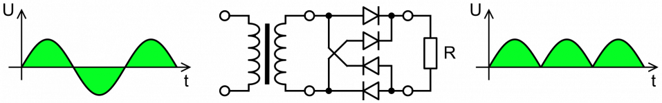
There is a very simple way to estimate the amount of ripple voltage from a diode feeding a capacitor, in turn feeding a load. Look at the ripple voltage with an oscilloscope, and you find it has nearly a sawtooth waveform. We can enormously simplify our calculation by pretending that it is exactly a sawtooth waveform, so that's what we'll do.
The "teeth" have a height equal to the ripple voltage (let's call it Vr). For a bridge or full-wave rectifier circuit, the ripple voltage teeth have a "width" (time duration) equal to one-half the period of the incoming AC. Since period of a waveform is (1/frequency), half that is 1/(2f).
Now we can estimate the slope of the sloping edge of each "tooth", using the simple formula used by carpenters and construction crews everywhere (slope = rise/run). Rise equals Vr, run equals 1/(2f), so rise/run equals (2 x Vr x f).
What we've just calculated has units of (ripple) volts per second; by definition, this is the rate of change of voltage with time.
Next we need the basic definition of what a capacitor does: the current (I) through a capacitor (C) is given by I = C x (rate of change of voltage across the cap).
We've already calculated the rate of change of voltage (it's the slope of the ripple voltage sawteeth), so we can put the two pieces together:
I = C x 2 x Vr x f
What we are interested in is the ripple voltage (Vr) as a function of the current draw (I). Rearranging the above equation gives us
Vr = I / (2 f C)
And there we are. Given the current draw (I), and size of the cap in Farads (C), and the frequency of the AC (f), we can now easily calculate the approximate ripple voltage.
In this case, f = 60 Hz, and C = 4100 uF = 0.0041 Farads. For a one-ampere current I, then,
Vr ~ 2 volts peak-to-peak.
Okay. So if we use a 4100uF cap in a country with a 60 Hz AC mains frequency, we get 2 volts of ripple per ampere of current draw.
Here comes the crucial bit!
Imagine we were trying to make a 5-volt power supply, supplying 1 amp of DC current, using one of these 4100 uF caps, and a 60 Hz AC mains frequency. For a 5 volt power supply, 2 volts of ripple would be intolerable. The voltage would drop from 5V all the way down to 3V every 8.3 milliseconds. Peak-to-peak ripple voltage is about 40% of the intended DC power supply voltage. That is intolerably huge.
Now imagine we were trying to make a 450-volt power supply, using the same cap, same AC frequency, same 1-amp load current. 2 volts of ripple on top of 450 volts DC is tiny. The voltage falls from 450 volts to 448 volts every 8.33 milliseconds. This is a tiny ripple voltage of less than one-half of one percent!
As you can see, "we need 1000 uF per ampere of current" makes a very poor guideline. That guideline is completely inadequate if you're making a relatively low-voltage power supply, and the same guideline is enormously excessive if you're making a high-voltage power supply.
Just as Jules Verne promised, a little algebra is a very handy thing!
-Gnobuddy
These values are used in many (modern, nothing old fashioned here) UPS systems and power inverters and in most cases a few are used in parallel and then also symmetric in modern "direct drive" UPSes. They are only usable when they are new/unused as these wear out in UPS systems. Contrary to audio UPS systems need new AC and DC caps every 50.000 hours (depending on brand/type) as they are energized 24/7 for years. They tend to fail when not being replaced. Mistakes with these can cause severe issues! Also with new ones most brands have a mode to power them up slowly as a new but faulty one may cause spectacular effects.
If one has the space in a casing they can be used for audio but make sure to have a discharging resistor or better a few in parallel. Also a text should be there warning for lethal voltages even when not powered on. Never ever make the mistake of working in the device without checking/measuring the voltage over the capacitor (should be less than 10V). When being taken out of use they should have a discharge resistor connected permanently. Nothing exxagerated: the use of safety goggles and insulating gloves is recommended when working with high voltage high value capacitors.
If one has the space in a casing they can be used for audio but make sure to have a discharging resistor or better a few in parallel. Also a text should be there warning for lethal voltages even when not powered on. Never ever make the mistake of working in the device without checking/measuring the voltage over the capacitor (should be less than 10V). When being taken out of use they should have a discharge resistor connected permanently. Nothing exxagerated: the use of safety goggles and insulating gloves is recommended when working with high voltage high value capacitors.
Last edited:
The calculations are right but .... a 5V PSU is rarely constructed of a 5V transformer 🙂 Now where did that guideline/rule of thumb come from?Imagine we were trying to make a 5-volt power supply, supplying 1 amp of DC current, using one of these 4100 uF caps, and a 60 Hz AC mains frequency. For a 5 volt power supply, 2 volts of ripple would be intolerable. The voltage would drop from 5V all the way down to 3V every 8.3 milliseconds. Peak-to-peak ripple voltage is about 40% of the intended DC power supply voltage. That is intolerably huge.
Now imagine we were trying to make a 450-volt power supply, using the same cap, same AC frequency, same 1-amp load current. 2 volts of ripple on top of 450 volts DC is tiny. The voltage falls from 450 volts to 448 volts every 8.33 milliseconds. This is a tiny ripple voltage of less than one-half of one percent!
As you can see, "we need 1000 uF per ampere of current" makes a very poor guideline. That guideline is completely inadequate if you're making a relatively low-voltage power supply, and the same guideline is enormously excessive if you're making a high-voltage power supply.
Just as Jules Verne promised, a little algebra is a very handy thing!
-Gnobuddy
With old text book stuff a 9V transformer was used for 7805 IC's as these had 3V dropout voltage then. The rule of thumb here with 50 Hz mains voltage was to use 2000 µF/A. In practice this would be a 2200 µF cap with a tolerance -20 ... +50% nearly always being in the + range. This worked out OK for those that did not calculate but used the rule of thumb "2000 µF/A". In other words, the rule of thumb worked for regulated DC voltages with 78xx series IC's and the then standard transformer voltages in the low voltage ranges i.e. 9 for 5V output, 12 for 9V output, 15 for 12V output etc. As the maximum current of 78xx was 1A the guideline simply worked.
Last edited:
It's a good question. Accelerating smoothly over the entire length of the barrel will certainly lower the G forces. But will it lower them sufficiently?But surely it is not 100G if it is continually accelerated over the whole length of the barrel, like the video at the start of the thread?
Physics and algebra to the rescue!
For an object starting from zero velocity, and ending up at velocity "v" after being accelerated with a uniform acceleration "a" for a distance "s", Newton's laws of motion tell us that: v^2 = 2 a S.
We can rearrange this to find "a": a = v^2/(2S) <-----equation 1
These equations expect that v,a, and S are in units of metres/second, metres/second squared, and metres respectively.
Okay. So you're suggesting that "S", the length of the gun barrel, should be 2 km, which is 2000 m....the 'gun' could be very long, say 2km up the side of a mountain...
We need to be careful about the "up the side of a mountain" bit. Remember that it is the upwards velocity of the bullet that must reach 25000 km/hr. Shooting it sideways at 25,000 km won't do us any good at all.
More precisely, what we care about is the vertical component of the bullet's velocity, which must equal 25,000 km/hr for the bullet to leave earth. If the gun barrel lies at a relatively low angle with respect to the horizontal, that lowers the vertical component of its velocity (most of its velocity is horizontal rather than vertical). We can compensate by making the bullet go even faster, but this worsens our excessive acceleration problem...
Let's consider a halfway angle between horizontal and vertical, i.e. 45 degrees. In this case, we would have to shoot the bullet out of the gun at (square root of 2) x 25000 m/S, to give it sufficient upwards velocity. That's about 35355 km/hr.
We must convert that to metres/second. There are 1000 metres in a km, and 3600 seconds in an hour, so we come up with v = 35355 km/hr = 9821 m/S.
Now we can calculate the acceleration "a" from equation 1:
a = v x v / (2 S) = 9821 x 9821 /( 2 * 2000) = 24112.7 meters/second squared.
To convert this into "G", we divide by the earths acceleration due to gravity, which is 9.81 metres/second:
a (in Gees) = 24112.7/9.8 = 2458 G

So it looks like you'd need an average acceleration of nearly 2460 Gees, maintained over a 2-kilometer length inclined at 45 degrees, in order for the projectile to achieve escape velocity. Needless to say, human cargo would be crushed to a thin layer of red pulp by that sort of G force. 😱
The answer I came up with (for average G) is so high, I wondered if I'd made some simple arithmetic error. So I tried doing the calculation from an entirely different approach. Suppose a human can tolerate 10 Gees for the entire length of the launch. Suppose this acceleration is vertically upwards, i.e. the most efficient direction to achieve escape velocity. Suppose the exit velocity is 25,000 km/hr. Over how long a distance does this 10G acceleration need to be maintained, in order to reach 25,000 km/hr?
We can simply re-arrange equation (1) to make "S" the subject of the formula: S = v^2/(2 a)
"v" is 25000 km/hr, which is 6944 m/S.
"a" is 10G, which is roughly 98.1 m/S^2. So (2 a) is about 196 m/S^2.
The answer is: a = 245765 metres, or roughly 246 KILOmetres!
In other words, to bring average acceleration down to 10G, and still build up enough speed to leave Earth entirely, we would need a gun barrel nearly 250 kilometres long (that's roughly 154 miles)!
I was a little boy when the moon launches were made, so I never thought about this in this much detail before. But if we think back to the video footage of the moon launches that we've all seen, the astronauts were subjected to almost unbearable G forces, all the way from launch through the entire earths' atmosphere (roughly 100 km, or 60 miles). And it didn't end there, as 2nd and 3rd stages again subjected the crew to extreme G forces over hundreds more kilometres.
So the crew in the lunar missions were in fact accelerated to full speed over a distance of hundreds of kilometres.
That gives me a little more confidence in my quick back-of-the-envelope calculation that says you need 250 km of 10G acceleration to reach escape velocity.
Unless I made a massive arithmetic error somewhere, it seems a 2-kilometre gun barrel wouldn't even begin to be long enough. We need a gun more than a hundred times longer than that, pointed vertically upwards. Only Elon Musk and his mindless droid-followers would think that was a practical idea. Hey, mebbe he could shoot his Mars-cult victims to the Red Planet using a 200-km phallic symbol with the word "Musk" painted in 10km-high letters on the side. 🙄
Thinking about that a bit more, Musk could simply build his Hyperloop super-train aimed at Mars. Musk-followers could ride the Musk train straight to the Red Planet. 🙄
In a nutshell, the concept of using enormous violence to shoot projectiles into space seems pretty much a non-starter.
Interestingly, a much gentler concept - float a rocket to the edge of the atmosphere dangling from a big helium balloon, then fire it from there to even higher altitudes - does work. But this "rockoon" concept has some of its own problems, most notable, uncertainty about the launch position, as balloons tend to be carried unpredictably by the wind: https://en.wikipedia.org/wiki/Rockoon
-Gnobuddy
Last edited:
Very odd. All the transformers I've seen were specified by RMS voltage, not peak voltage. A 9V transformer will have roughly 12.7 volt peaks, and after the rectifier diode has dropped roughly 0.7 volts, will produce a nominal 12 volts DC.With old text book stuff a 9V transformer was used for 7805 IC's as these had 3V dropout voltage then.
This is a full 7 volts higher than the 5 volt output of a 7805, and the resulting excessive power dissipation would keep the 7805 from getting anywhere close to its 1-amp current limit, even with a good heatsink.
A 6.3V AC RMS transformer is a better match to old-school 7805 ICs, typically producing more than 8 volts filtered DC at the input to the 7805.
But not to lose sight of the big picture: the point is that (a) We usually care about ripple voltage as a percentage of the DC voltage from the power supply, and (b)This means you need fewer microfarads-per-amp as the power supply DC output voltage increases.
-Gnobuddy
No. Rocket mass declines over time. The big old rockets lifted off the pad like a Yugo with 2 bad plugs, but gaining speed as fuel was used. At about 3 minutes the Gee got distressing, the "throttle-down" point. So the 1960s astronauts had increasing Gee until they greyed-out, throttle-back, Gees rising again until flame-out. And then repeat for stage 2.the moon launches that we've all seen, the astronauts were subjected to almost unbearable G forces, all the way from launch through the entire earths' atmosphere
You have mains tolerances (+/- 10 %), ripple voltage, rectifier voltage drops that are well above 0.7 V per diode when you have current peaks of a few amperes flowing through a normal rectifier diode, two diodes in series when using a Graetz bridge rectifier, voltage drops across the transformer's wire resistance that are greater with peaky currents than with sine waves. Account for all that and you need about 8 V to 9 V nominal RMS transformer output voltage for a 7805. You can just get away with 6.3 V when you use Schottky diodes and a low-drop regulator.Very odd. All the transformers I've seen were specified by RMS voltage, not peak voltage. A 9V transformer will have roughly 12.7 volt peaks, and after the rectifier diode has dropped roughly 0.7 volts, will produce a nominal 12 volts DC.
This is a full 7 volts higher than the 5 volt output of a 7805, and the resulting excessive power dissipation would keep the 7805 from getting anywhere close to its 1-amp current limit, even with a good heatsink.
A 6.3V AC RMS transformer is a better match to old-school 7805 ICs, typically producing more than 8 volts filtered DC at the input to the 7805.
But not to lose sight of the big picture: the point is that (a) We usually care about ripple voltage as a percentage of the DC voltage from the power supply, and (b)This means you need fewer microfarads-per-amp as the power supply DC output voltage increases.
-Gnobuddy
I agree with your statement about larger ripples at larger voltages.
Yes a 6.3V transformer will never work out with a 7805 and Gnobuddy makes a mistake with the rectifier diodes dropout. The 2000 µF/A rule of thumb combined with the old standard transformer voltages worked/works OK for the old fashioned 78xx series. Besides that no one cared about power loss/heat then. Still it is advisable to calculate matters as that is the core of right engineering and we have wonderful LDO regulators now that are far superior to 78xx/LM317.
The problem with reminding rules of thumb is that they often get taken out of context.
The mistake can be seen in this example. There are 2 diodes in series and with the old rule of thumb diodes were calculated as 1V dropout voltage each at maximum current which was then 1A for 1N4004. The 6.3V transformer /7805 combo will never work contrary to the guideline that worked automagically 😀
Attachments
Last edited:
Not dissing anybody, just thinking aloud:
* everybody does the RMS to peak conversion right
* most miss that diode drop is 1V or more at high currents, never generally assumed 0.7V
* almost all (99.5%?) completely ignore transformer DCR.
Which is worsened by charging current being made out of very narrow very high current peaks.
Oh well.
* everybody does the RMS to peak conversion right
* most miss that diode drop is 1V or more at high currents, never generally assumed 0.7V
* almost all (99.5%?) completely ignore transformer DCR.
Which is worsened by charging current being made out of very narrow very high current peaks.
Oh well.
- Home
- Amplifiers
- Tubes / Valves
- 4100uF/450v *BIG* capacitors... any use?