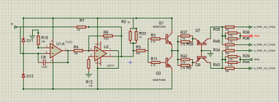
Hello. I work with amplifier 4000.1. Driver board, part of the circuit and oscillogram attached. The problem is that the meander disappears at the output of LM311 when I solder the output 24N40F. Changed LM311, TL 072 and IR21844. What would you recommend?
Attachments
-
 Board.jpg765 KB · Views: 460
 -
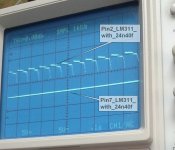 Pin2_LM311_with_24n40f.jpg557.2 KB · Views: 141
 -
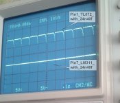 Pin1_TL072_with_24n40f.jpg540.8 KB · Views: 128
 -
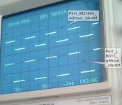 Pin1_IR21844_without_24n40f.jpg548.7 KB · Views: 386
 -
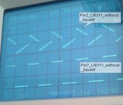 Pin2_LM311_without_24n40f.jpg518 KB · Views: 387
 -
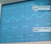 Pin1_TL072_without_24n40f.jpg520 KB · Views: 424
 -
 4000.1.png33 KB · Views: 453
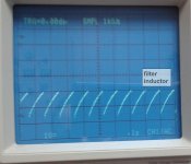
With the output FETs in the circuit (at least one per drive circuit) do you have any DC on the output filter inductor inductor before the relay?
Do you get rail to rail oscillation on the output transistors with the output transistors in the circuit?
Do you get rail to rail oscillation on the output transistors with the output transistors in the circuit?

On the filter inductor voltmeter shows minus 1.6 Volt. The waveform at the same point applied.
Clarification: the first couple seconds of operation of the amplifier is a square wave at the output of the LM311 is present.
The components inside the feedback loop are going to have the same signal after the output is enabled.
Do you have rail-rail output on the output transistors at any time?
Do you have rail-rail output on the output transistors at any time?
English is not my native language, sometimes I do not understand something about your questions. For example: "Do you have a rail-rail output on the output transistors at any time?" Do you mean to check the ripple on the rails plus and minus the output transistors? If not, please ask otherwise. I hope for your understanding
Go the following location on the basic repair page. If it does not load the r-r oscillation section, simply reload the page.
Basic Amplifier Repair
Basic Amplifier Repair
Do you get rail to rail oscillation on the output transistors with the output transistors in the circuit?
No. Only DC +/- 104Volt (divider by 10 is switched )
Attachments
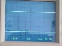
I went through all the modes in the Source, Coupling, and Slope and Level and Holdoff. The oscillogram does not change.
auto-normal - auto
tv - try both
source - input 1
holdoff - don't know
start with trigger level centered but roate through full range after each change of other settings
timebase - magx1
tv - try both
source - input 1
holdoff - don't know
start with trigger level centered but roate through full range after each change of other settings
timebase - magx1
TV is a synchronization by a television signal. Put in OFF. Perry, what kind of oscillogram should I see?
Sometimes, the tv sync can make the scope trigger when nothing else helps.
You should see something like you saw in the r-r section of the basic repair page. Right now, it's showing that you have r-r oscillation but you need to determine why the scope won't trigger. If you have a switchable probe, set it to 10x and set the scope vertical amp to 1x.
You should see something like you saw in the r-r section of the basic repair page. Right now, it's showing that you have r-r oscillation but you need to determine why the scope won't trigger. If you have a switchable probe, set it to 10x and set the scope vertical amp to 1x.
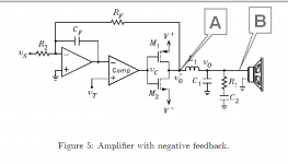
Yes. Point A. At point B, there should be no square wave and generally only a small residual of the carrier wave in something that roughly looks like a sine wave.
Will your scope trigger on the power supply FET drains?
In the earlier images, you were using the digital storage. Why did you switch to analog?
In the earlier images, you were using the digital storage. Why did you switch to analog?
- Status
- Not open for further replies.
- Home
- General Interest
- Car Audio
- 4000.1