Grant...........That' a pretty interesting drop, I will put the components into my simulation.........I have the sim with my actual component values saved, so it won't be a problem to do quickly.......I will report my findings..Thank you very much for your effort........Tonite, also I will probably play with the link Tinitus graciously provided............Andy...The Drivers I am using are the Peerless SLS 830669 12 inch.....Seas CA15RLY midbass......Seas 27TDFC tweeter...............You can see the crossover schematic a few pages back for reference...........Tinitus, I appreciate your comment, and you are correct, and have a very keen perception of where I am at...........I will continue to be diligent and exercise patience, but I do believe I have only begun fine tuning Frankie, but this is the fun part.......................Omni
Well, notches are kind of new to me too, but I think that in a paralel notch fore FR "shaping", the inductor is big and the cap is small ... if you do it the other way round with big C and small inductor, its intended fore impedanse peaks
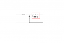
Grant....Tinitus...........It appears to me that probably the notch of choice will be a parallel filter situated in series to the driver........When I modelled series notch filters situated in parallel to the driver, impedance appeared to go a bit low, possibly in the danger zone..............omni
Tinitus,
Omni's SLS notch centred at 2130 Hz is narrow (higher C and correspondingly lower L), but it seemed to work best like that. But I'll halve the C and try again... with L = .02534464 / ( f X f X C )
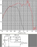
Here's your notch centred at 4380Hz...I used Omni's CA15 in box data with no other filter.
Omni, I'll resim your networks with new filters if you wish. It will be interesting to see how much the 2k peak diminishes... grant
Omni's SLS notch centred at 2130 Hz is narrow (higher C and correspondingly lower L), but it seemed to work best like that. But I'll halve the C and try again... with L = .02534464 / ( f X f X C )
Here's your notch centred at 4380Hz...I used Omni's CA15 in box data with no other filter.
Omni, I'll resim your networks with new filters if you wish. It will be interesting to see how much the 2k peak diminishes... grant
Attachments

Thanks fore the sim, and wow, it looks like a real effective notch 🙂
BTW ... seems you have simmed on midrange ... I forgot to mention that I use it on 4ohm woofers, so ofcourse component values would be different, but I guess I wouldnt use THAT on a wellbehaved midrange, as it seems to nearly shut down the driver, might be good on peak troubled drivers though
BTW ... seems you have simmed on midrange ... I forgot to mention that I use it on 4ohm woofers, so ofcourse component values would be different, but I guess I wouldnt use THAT on a wellbehaved midrange, as it seems to nearly shut down the driver, might be good on peak troubled drivers though
Hey Omni,
I took Tinitus' advice and tried it a bit wider... now it doesn't look too shabby, but its a real sledgehammer approach, same as your 7.7mH coils name! haha. I have no idea as yet what the impedance
implications would be. Thanks Tinitus, for your suggestion, grant
I took Tinitus' advice and tried it a bit wider... now it doesn't look too shabby, but its a real sledgehammer approach, same as your 7.7mH coils name! haha. I have no idea as yet what the impedance
implications would be. Thanks Tinitus, for your suggestion, grant
Attachments
Tinitus,
Maybe I should set up a theoretical data file that is dead flat from 20 to 20kHz, so that we can see how proposed filters affect response. Do you think this would be a good idea? Then we could see exactly how different filters work on a 'perfect' transducer, well maybe. grant
Maybe I should set up a theoretical data file that is dead flat from 20 to 20kHz, so that we can see how proposed filters affect response. Do you think this would be a good idea? Then we could see exactly how different filters work on a 'perfect' transducer, well maybe. grant
NICE!
NOW you could try a "shunt" resistor on the 80uf 😉
Still, the configuration I suggested has proven to sound better, that is at least in my own setup
NOW you could try a "shunt" resistor on the 80uf 😉
Still, the configuration I suggested has proven to sound better, that is at least in my own setup
Tinitus,
Thanks! From memory, was it a 2 ohm on the 80uf cap? I can't find Omni's xo just now, and maybe his 'xo-parts-cost-$' just exploded? Thanks, Tinitus, for what its worth, I'll simulate things for you, but Speaker Workshop 'sims' are quite easy when you understand it. I only know a very small part of it! best wishes from grant
Thanks! From memory, was it a 2 ohm on the 80uf cap? I can't find Omni's xo just now, and maybe his 'xo-parts-cost-$' just exploded? Thanks, Tinitus, for what its worth, I'll simulate things for you, but Speaker Workshop 'sims' are quite easy when you understand it. I only know a very small part of it! best wishes from grant
"shunt" resistor ?
It seems I always end up with values around drivers DC
And that counts fore my notches too
I dont know why, but at least to me it makes sense
I dont believe it to be accidental allthough it could seem like it,
It always end up sounding better that way, and if it dont I correct in other places, untill I get the desired result(sound)
Tinitus,
ok, 8 ohms on 80uF cap then? I just found Omni's xo and it was 2 ohms before? You're call, over to you.. cheers my friend! grant
ok, 8 ohms on 80uF cap then? I just found Omni's xo and it was 2 ohms before? You're call, over to you.. cheers my friend! grant
Well, 2ohm is the value Omni found to work in his curcuit
But it was before the notch
Well, drivers DC I guess is around 5ohm, so I wouldnt use much less
But you have very nice tools to help you, and I dare not argue with that
But with several years of working with especially this xo, I believe to have found some pattern, in how it reacts to certain changes and not the least, how it sounds
But at least to me it would be interesting to see you experiment with this, now you have learned to use simulation
BTW, at the moment Omni finished his xo, I was not completely satisfied with my own ... that I am now, well mostly
What I think you need to realise is that the final voicing of a speaker is very much affected by the room, your own whims and hearing capabilities, and even by the gear you use to feed the signal ie the CD player, turntable, amplifier etc, and the interaction between all these parts of the system.
As such, there is no such thing as an absolutely correct x-o network.
As such, there is no such thing as an absolutely correct x-o network.
Andy,
Your advice is great... thanks. I'm still deciding on your excellent driver recommendations! I was very impressed with your Juke's even unfinished sound, so they must be superb now! Your yellow glass fibre MG18SK's sounded great.
Regarding your posts # 701 and 703, thats very interesting about series crossovers! I feel comfortable using Speaker Workshop only for xo modeling , so I guess its time to apprehensively try it for 'series'. The superb sound of your designs using series crossovers, is a very compelling reason to try it.
Just for fun, I'm still wondering if the TangBand W4-1337SA could be used full range with series xo with either my P25 woofers or 4 Jaycar CW-2136's. I think Sreten said once the P25's Xmax was 4mm.
www.tb-speaker.com/detail/1230_04/w4-1337sa.htm
Can series accommodate individual driver notch filtering as in the TBand peak? I'm new to this stuff but you and Sreten mention mixed topologies so I guess it can be done. ...Oops, I'm raving on again! ...thanks, grant
Yes, a series x-o can have notch filters etc, but in my mind it is against my ideals.
If you are using a series x-o, particularly a low order one like I prefer, it is because you have selected drivers specifically for the purpose. ie you aim to have minimal or no corrections required.
Another way is to read through the LBI series stuff that John Risch allowed me to put on my site.
If you are using a series x-o, particularly a low order one like I prefer, it is because you have selected drivers specifically for the purpose. ie you aim to have minimal or no corrections required.
Another way is to read through the LBI series stuff that John Risch allowed me to put on my site.
Hi all,
I just found this interesting site: www.phys.unsw.edu.au/jw/hearing.html
Tinitus, there is a section on that site about violin acoustics which might interest you?
Andy, thanks for you comments. I'll re-read the 'JR' stuff on your site
Omni, how is Frankie sounding now please? ...........grant
I just found this interesting site: www.phys.unsw.edu.au/jw/hearing.html
Tinitus, there is a section on that site about violin acoustics which might interest you?
Andy, thanks for you comments. I'll re-read the 'JR' stuff on your site
Omni, how is Frankie sounding now please? ...........grant
Grant, Frankie is still sounding himself, upper end is opening up a little bit.............Maybe capacitor break in?.......I don't know.........I went to the link Tinitus provided and played with the frequency flattening tool.............I did several "widths" of notchs and made copies of them all including component part values............Next step is to insert these results into my current crossover simulator............I named it Frankietweaks...............Also, Grant, I am gonna insert your values into it as well and see what it does........Something I noticed while I was working with the frequency flattening tool was that the inductor value appeared to hover in the range of .35mH to .55mH..............Tinitus, you mentioned for me to keep an eye on DC resistance here, so as to maintain good control on the woofer............I think these values shouldn't add too much series resistance..........What do you think?.............Resistor value stayed at 8 ohms for the most part.............The capacitor varied the most, so it's gonna take some time to observe the several combinations I have come up with......................Much more to talk about, but I wanna get a read on these initial experiments.............I will be in touch........Omni
- Status
- Not open for further replies.
- Home
- Loudspeakers
- Multi-Way
- 3way XO help greatly appreciated!