Hi,
Omni...its near perfection, but I think your series coil on midrange is a tini bit too big..... but its easy to wind off a little bit .....you seem to have grown fond of 2 ohmm resistors 😀
Good work that is
BTW ...Grant .... It could be interesting if you simulated something like the `"PoorMansStrad" .... just to see what would happen
🙂
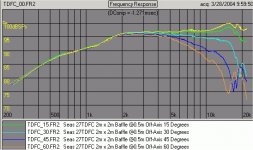
Omni, I found a site: http://www.speakerdesign.net/raw/rawdescr.html
that has measurements of your 27TDFC's, so I thought you might like to compare it with your results? It also has FRD/ZMA files! I hope this is interesting for you? (its in 'tweeter large', I think, if not I can
email)
Btw, from lots of reading, I think maybe the 27TFFC and MCA15RCY with my old Vifa P25's could be ok? But Troels infers inductors DCR's of less than 0.3 Ohms which will be really expensive! They would
cost more than a driver! Hmm, what to do? grant
Attachments
Sreten,
Are you still here? Any comments you have on my last few posts would be extremely appreciated! thanks, grant (please excuse the silly one!)
Are you still here? Any comments you have on my last few posts would be extremely appreciated! thanks, grant (please excuse the silly one!)
Grant .... inductor 0.3 ohm .... theres also a 0.2 ohm series resistor ..... and its a different driver so other things may change as well .... cabinet size, porting, crossover...
Grant, I checked out the site you posted and observed the TDFC graph...............It looks similar to the manufacturers plot and overall, I think they are accurately representative of the TDFC. The only difference being is that the graph on the site you posted appears to be a little bit smoother throughout............I am heartened by the validation..............Tinitus, thank you for your observations. I will be tweaking a bit today, as I have been studying these graphs diligently, and believe am gaining a bit of understanding as we have progressed.............What is your thought on the series resistor on that midbass series inductor?........We'll be in touch......Respectfully...........Omni
Grant, Minimum impedance is at 5.5 ohm.....The crossover program does show phase graphs which I can view, however, I don't know how to interprate them, or know what to look for.........Can you and Tinitus school me on Phase? Thank you........Omni
Phase...... well, thats the tricky part of making the 3-way into a coherent speaker with correct timing ..... I use my ears .... funny thing, all resistors are now around drivers DCimpedance .... coincidense ...?
You may also consider that EVERY component affects phase
The resistors .... in series with mid ?
Apart from attenuation ..... when you raise impedance, inductors will need to be bigger and condensators smaller .... and theres no need for unnessesary big inductors ..... when possible, smaller always sound better
But two resistors in series will not sound the best ..... allthough a series resistor might take away some peaking/ringing
Tweeter ..... You might need L-pad attenuation on tweeter
BTW....if you make mids series inductor a bit smaller, you might want to make tweeter paralel inductor smaller too ... and maybe bigger resistor
Oh yes, make it a habbit of using standard values.... it simply sounds better with just one component in each place
It would be very nice if you could make a paralel notch in series with bass, above 1khz
Tinitus: Here's the deal....I am SO excited right now, I am beside myself, I got goosebumps. Heres why.............I fidgeted around with that inductor, and just a small change {it's .84 now} brings UP that slightly lowered summed response {at the mid/tweet crosspoint} INTO LINE with the rest of the response. Also played with that 12uF cap that's in the lowpass section of the midbass and it brought that nasty dip UP about 3/4 dB........... New cap is about 13uF......Now total response only varies about 1 to 1.5 dB across ENTIRE range.............I am starting to GET IT, man...........I realize this is only a simulation, and real world results may vary a bit............HOWEVER......I believe that I am at a point to where I can build a crossover, and then tweak by ear, because I am at a point to where the tweaks on the simulations are more informed, so to speak, and the results of those tweaks are positive, and most importantly, the tweaks are only MINOR changes in components............I will be able to buy a few extra caps in order to facilitate this.................Also, on the crossover circuit picture, I forgot to insert the 2 ohm series resistor on the tweeter..............So it's there..............Also, the standard values you mention are extremely close to the ones that are simulated, so I think we will be in good shape there. Thank you very much for your support, and I look forward to more good stuff on this thread..................Respectfully...........................Omni
grantnsw said:Sreten,
Are you still here? Any comments you have on my last few posts would be extremely appreciated! thanks, grant (please excuse the silly one!)
Hi,
Basing your choices on the PMS is a good idea.
I though yout mid volume was fixed at 1.5L ?
The midrange volume you can do nothing about, TG is following the
current fad for reflexed midranges, it is a fad. More volume would be
good to damp the backwave, but probably not worth the rebuild.
The PMS mid/treble crossover should be near, but due to baffle size
of the PMS the bass / mid c/o and baffle step arrangements will not
suit a narrower speaker, and the mid/treble level may need reducing.
🙂/sreten.
tinitus said:Hi, ... look at the graphs you posted from Troels
Look at the round "shoulders"....thats what I was talking about
BUT you will also see a very small dip at the point where bass tweeter meet, though I am sure its insignificant its there
A great danish innovator mr. Steen Duelund, who is sadly not among us any more, made his own filter to take care of this - put simple, the whole filter was calculated from this exact point
This filter is examined at Linkwitz - but I guess we would need the skills of Sreten to understand any of it
http://www.linkwitzlab.com/crossovers.htm
Hi,
I can't really add much to SL's excellent discussion of the principles
and how to approximate the 8th order functions with 4th order
functions, it is an alternative to 4th order 3-way L/R alignments.
But deriving the correct acoustic alignments is difficult when not
using active filters, and like other theorectical topologies the
electrical and acoustic effects of the drivers and cabinet are
completely ignored in the principles. It is including these effects
in the c/o design that is the first step to getting the c/o to work,
and for passive c/o's it is usually a case of using the topology
that seems to work best for that case rather than setting out
to use a specific topology for the acoustic responses.
🙂/sreten.
Tinitus,
thanks for your comments. Yes I would like to sim a modified PMS with the P25 woofer in my reflex boxes. It would be very interesting to see the results.
Omni,
The 5.5 minimum Z seems good to me, but on page 33? Sreten mentioned the 'complex' nature of Z and a reference 'TinaTi' to check it, but from memory its a huge download (I tried several times but got disconnected).
Re: Phase... back on page 32? again Sreten kindly informed me that the electrical phase was the issue, and he also pointed out that I posted an acoustic phase graph with a log F-axis which gave rise to the apparent abrupt vertical 'jump'. Thanks Sreten! I don't know if SWorkshop or Jeff Bagby's s/w will show electrical phase? Congratulations on your latest post!
Sreten, many thanks!
I'm glad to hear the PMS mids and tweeters , ( with the P25's ) could form the basis of a good home-brew system subject to modifying the xo as you mentioned. Yes my mid box volume is 1.5L closed. Also, thanks for 'the current fad for reflexed midranges'. So , after all this time it looks like my final driver selection is done: 27TFFC and MCA15RCY <--- your recommendation is great! ...grant
I'm glad to hear the PMS mids and tweeters , ( with the P25's ) could form the basis of a good home-brew system subject to modifying the xo as you mentioned. Yes my mid box volume is 1.5L closed. Also, thanks for 'the current fad for reflexed midranges'. So , after all this time it looks like my final driver selection is done: 27TFFC and MCA15RCY <--- your recommendation is great! ...grant
Hi,
TinaTi is a 19MB download. It does have a very handy impedance meter.
The trail version of Basta is pronbably better as it models the drivers better.
Simply put say 6 ohm impedance with a 90 degree phase angle is as bad as a 3R resistive load.
So the impedance can be twice as bad as it appears. Phase angles must be checked.
Generally anything more that 45 degrees at low impedances is poor.
🙂/sreten.
Hi Omni, just for fun I found another 27TDFC review...(vs 27TDC non ferro-fluid?)
http://www.markk.claub.net/Testing/Tweeter3/seas_comparison.htm
'the bottom line' --->
Overall, a toss up between two very good tweeters. A bargain in their price range. ..grant
http://www.markk.claub.net/Testing/Tweeter3/seas_comparison.htm
'the bottom line' --->
Overall, a toss up between two very good tweeters. A bargain in their price range. ..grant
grantnsw said:he also pointed out that I posted an acoustic phase graph with a log F-axis which gave rise to the apparent abrupt vertical 'jump'.
Hi,
The vertical jumps are caused by the phase angle going though points
that are common to the bottom and top axis, nothing to do with log F.
There is no abrupt change, at each "jump" the lines should be moved
so they are continuous. Another way of looking at it is phase is shown
on a cylinder opened up, so you need to add revolutions.
🙂/sreten.
Hi Sreten, I'm still considering other opinions, lol
Re: the MCA15RCY...this link is interesting?
http://www.markk.claub.net/Testing/Midrange1/midrange_test_data.htm Quote: Comments: (edit..my emphasis with *'s)
I'm not going to tell you exactly which is best. It depends on your application. The M15 and MCA15 are pure mids and *struggle* with nonlinear distortion at 150 Hz. On the other hand, they have good nonlinear distortion at 400 and 850 Hz, and have the smoothest FR/best linear distortion numbers above 1k. As a pure mid, *the MCA15 is probably the best value*. The M15 may be marginally better, but not by much and is very expensive. The W15, RS150, and 5W are more midwoofers. In terms of nonlinear distortion, I think overall the rankings would be W15, RS150, M130, and 5W. The W15 also has very good linear distortion/FR up to 1400. Crossed low, the W15 would be an excellent driver.
Let me say, though, that NONE of these drivers really does an adequate job reproducing low bass. While the W15 nonlinear plot looks great above, increasing the drive level just one more dB caused the driver to start audibly distorting with some rub/buzz type noise. While the W15 would be great in a 2 way at low volumes, you're kidding yourself that you can get any realistic bass output out of it. Likely you'll just be faked out by the 2nd and 3rd order products as you increase the volume.
So, it looks like I should still go with it? Any comments please? Thanks , grant
Hi Sreten,
Yeah, I'm dumb, lol (don't want to be! ) but I can't understand this? quote:
"Simply put say 6 ohm impedance with a 90 degree phase angle is as bad as a 3R resistive load.
So the impedance can be twice as bad as it appears. Phase angles must be checked. Generally anything more that 45 degrees at low impedances is poor".
Maybe, I'm a 'lost cause'? I just WISH I had the capacity to understand! If this is 'simple' then I've totally lost the plot! and I'm sorry to bore you with my inane questions!...grant
(maybe some work on my part will help me out here?)
Hi,
90 degrees = pure inductive or capacative load = no power dissapation in the load.
Consequently the amplifier needs to dissapate all the power that
should be dissapated by the load as well as its normal dissapation.
So it gets much hotter, like its driving a lower impedance load.
Like I said low impedance + high load phase angles = trouble.
Note the load on the amplifier cannot exceed +/- 90 degrees.
All the above is about amplifier design. Good loudspeaker design
keeps the load phase angle low at points the impedance is low.
Read up on power factor and power factor correction for motors if you like.
The MCA15RCY will be fine in your midrange application.
🙂/sreten.
Thanks Sreten,
I will download the Basta trial again and see if it will run again.
Re: 'no abrupt change' I like your very good analogy of adding revolutions to a cylinder... I see!
Thanks again re the MCA15, interestingly the Seas specs show it was tested in a 20L closed box. Would this then corroborate your observation of reflexed midranges being the current fad?
Re: power dissipation and complex impedance, I think I get it now ! Thanks!
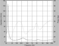
So, as you said the goal is less than 45 degrees at low impedance. I've attached a graph of (a previous xo for Omni) phase and
impedance from Speaker Workshop. Is this the electrical phase? I assume its ok, because the impedance doesn't seem too low and the phase is about +- 30 degrees from 50 to 20kHz. grant
I will download the Basta trial again and see if it will run again.
Re: 'no abrupt change' I like your very good analogy of adding revolutions to a cylinder... I see!
Thanks again re the MCA15, interestingly the Seas specs show it was tested in a 20L closed box. Would this then corroborate your observation of reflexed midranges being the current fad?
Re: power dissipation and complex impedance, I think I get it now ! Thanks!
So, as you said the goal is less than 45 degrees at low impedance. I've attached a graph of (a previous xo for Omni) phase and
impedance from Speaker Workshop. Is this the electrical phase? I assume its ok, because the impedance doesn't seem too low and the phase is about +- 30 degrees from 50 to 20kHz. grant
Attachments
- Status
- Not open for further replies.
- Home
- Loudspeakers
- Multi-Way
- 3way XO help greatly appreciated!