Hi Tinitus,
Regarding driver offset definition in (specifically) Speaker Workshop, I've read conflicting opinions, and agree that it must be 'sorted out' to achieve legitimate results. Maybe the SW help forum would be useful here. thanks, grant
Regarding driver offset definition in (specifically) Speaker Workshop, I've read conflicting opinions, and agree that it must be 'sorted out' to achieve legitimate results. Maybe the SW help forum would be useful here. thanks, grant
Grant, In terms of the crossover frequency, pertaining to the tweeter, my understanding is that it is wise to cross it over at a MINIMUM of 2 octaves above its' resonant frequency. The crossover separation or spread, as I construe it , is the difference between the lower crossover point and the upper crossover point. In this case one might choose a suggested ratio of 3.4 octaves, or 3 octaves. In other words, if you cross over at the lower end at a frequency of 300 and use 3.4 octaves,or Fh/Fl=10, your upper crossover point will be 3000......... For the TDFC, the minimum of 2 octaves above its' resonant frequency, for the tweeter point would put it at 2200 Hz. Using that figure to choose a crossover at the low end would put it at 220. That represents a 10=Fh/Fl, or a 3.4 octave spread between high and low crossover points. A bit low for the midbass to go. Using a 3 octave spread between crossover points would put a 300 Hz low end crossover point at 2400 Hz for the high end. A more reasonable point, which covers the 2 octave above tweeter resonant frequency minimum. However, this is just at minimum, for the tweeter. I chose 3000Hz because it is beyond the minimum, but low enough, still, to take full advantage of the TDFC performance characteristics. The driver excursion will not be too large to burden the tweeter. For all I know, the actual resonant frequency of the tweeter could be higher than the manufacturers stated specification.........and as we are all aware, drivers sometimes vary in their actual specs from what the manufacturer states. So if, for example, the TDFC resonant frequency was actually 600 Hz., then the minimum crossover frequency for that tweeters' resonant frequency would be at 2400 Hz............At 3000Hz, I still have a margin of safety...........Yeah man, your graphs indicate crossover frequency near 2000 in the upper xover region and around 400 in the lower xover region, and I don't understand why, since you used calculated figures for the components to render 300 and 3000Hz. Do you have any idea why this is?.........Tinitus, in response to your question on driver offset, heres's the deal. As per the users manual for the simulation program, I did this: Everything is considered relative to the tweeter, being that it is closest to the baffle. So that figure is put in at 0 {zero } midbass acoustic center, as measured from tweeter, is 3/4 inch behind 0, so I entered -.75 inch. The figure was converted into metric, then entered into simulator. The woofer measured 1.5 inches ahead of 0, due to my baffle slant, which, in an earlier post I mentioned my dissatisfaction with. So it is entered into the simulator at +1.5 of 0., converted to metric..........You mentioned in an earlier post not to despair, because you thought that it may turn into an advantage. At any rate, it appears that the final baffle slant of the actual cabinet was more than, what I designed, or what it looked like on paper. So it is obviously an issue that has served to complicate things..........However, as per my results on Bagbys 5.1 crossover designer, they seem to be accurate on the graphs, as far as the points of crossover , given the information I have to enter into the program.................Now all that's left to do is learn more about the series resistor idea, get back onto the simulation program, and tweak, tweak, tweak.............put more graphs up for you all to view, and keep in touch, listening to your recommendations, and tweak, tweak, tweak..............and enjoy every minute of it...........................Respectfully.........Omni
Omni,
The comments below, assume that a 300/3000 split is the ideal 'textbook' scenario. And given my latest *goof-up* I would strongly urge you to check anything I say! lol. Sreten's treatise on tweeter
excursion must also be considered, but unfortunately its still beyond me (can you help me out with this, when you get the time? I'd really appreciate it! ) Ok, here goes....
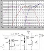
Mid LP: 0.56mH coil and 5uF cap --> resonance 3006.7 Hz.
Tweeter HP: 0.35mH coil and 8uF cap --> resonance 3006.7 HZ (uncanny, have I screwed up here? I DID triple check it!) But the lines on the chart crossed at 1920 Hz! Could it look different because of 'total acoustic' irregularities?
Now for Peerless, 8.6mH coil and 75uF cap --> resonance 198 Hz
CA15 HP: 6mH coil and 38uF cap --> resonance 333 Hz. But on the chart the lines appear to cross at 427 Hz. And the total response for all drivers looks very good.
Ok, given the same coil values for woofer and CA HP, lets get the resonance pretty close to 300 Hz. The Peerless cap is now 33uF, and the CA HP cap is now 47uF. Example attached. But look at what happens to the response! ( I arbitrarily increased Rzobels, hopefully to save the amp!, lol)
If I've made any further 'stuff-ups', I might just quietly disappear! hehe, grant
The comments below, assume that a 300/3000 split is the ideal 'textbook' scenario. And given my latest *goof-up* I would strongly urge you to check anything I say! lol. Sreten's treatise on tweeter
excursion must also be considered, but unfortunately its still beyond me (can you help me out with this, when you get the time? I'd really appreciate it! ) Ok, here goes....
Mid LP: 0.56mH coil and 5uF cap --> resonance 3006.7 Hz.
Tweeter HP: 0.35mH coil and 8uF cap --> resonance 3006.7 HZ (uncanny, have I screwed up here? I DID triple check it!) But the lines on the chart crossed at 1920 Hz! Could it look different because of 'total acoustic' irregularities?
Now for Peerless, 8.6mH coil and 75uF cap --> resonance 198 Hz
CA15 HP: 6mH coil and 38uF cap --> resonance 333 Hz. But on the chart the lines appear to cross at 427 Hz. And the total response for all drivers looks very good.
Ok, given the same coil values for woofer and CA HP, lets get the resonance pretty close to 300 Hz. The Peerless cap is now 33uF, and the CA HP cap is now 47uF. Example attached. But look at what happens to the response! ( I arbitrarily increased Rzobels, hopefully to save the amp!, lol)
If I've made any further 'stuff-ups', I might just quietly disappear! hehe, grant
Attachments
Omni,
Argh! Seems like I've done it again! Changing both Rzobel values at the same time as changing the capacitors, was not wise from a comparison viewpoint. The changed Rzobels did make a significant contribution to the altered response. I think what I should have done
for a more accurate comparison, would be to delete both Zobels, (using the initial capacitor values for woofer and mid HP as stated), and graph the response. Then (with both Zobels still deleted) change the cap values as mentioned and see the response difference. I hope you know what I mean.... grant
Sreten, Hi, thank you very much!
Given that a 2kHz 2nd order electrical xo is fine for the 27TDFC, may I ask what you might suggest for the Peerless/CA15 xo frequency? (assuming '2nd order electrical' on both). Are there other factors that need to be considered here? I assume 200Hz? then is appropriate. thanks, grant
Given that a 2kHz 2nd order electrical xo is fine for the 27TDFC, may I ask what you might suggest for the Peerless/CA15 xo frequency? (assuming '2nd order electrical' on both). Are there other factors that need to be considered here? I assume 200Hz? then is appropriate. thanks, grant
Omni, g'day!
You know what... that last chart is still +- 2.5 dB from 50 to 10kHz.
So, even in the 'worst case' you may not hear the difference, unless you have 'golden ears'! lol just FWIW, best regards, grant
You know what... that last chart is still +- 2.5 dB from 50 to 10kHz.
So, even in the 'worst case' you may not hear the difference, unless you have 'golden ears'! lol just FWIW, best regards, grant
grantnsw said:Sreten, Hi, thank you very much!
Given that a 2kHz 2nd order electrical xo is fine for the 27TDFC, may I ask what you might suggest for the Peerless/CA15 xo frequency? (assuming '2nd order electrical' on both). Are there other factors that need to be considered here? I assume 200Hz? then is appropriate. thanks, grant
Hi,
Depends on its Fb (mid enclosure size) , and the alignment of the loudspeaker.
The problem I assume is baffle step, your trying to get the transition
between the higher sensitivity woofer to the midrange to account
for the baffle step, this will depend on the width of the speaker.
An acoustic c/o point between the two of 200Hz would likely
be too low to achieve the above unless its a wide speaker.
🙂/sreten.
Omni, sound good
Grant, You are close to whats called a "filler driver" - which means that bass and tweeter almost reach each other, and mid is only filling in the gap, but ofcouse its not
Look at your response curve...
The high end of mid is low because of the 2ohm resistor AND you use a too big C in zobel, and at the same time using a small paralel C - I dont think its a good idea
Your lower end of mid is higher excactly at the frequency where tweeter and woofer crosses....... 😉
Sreten, thank you...
Re: "Fb (mid enclosure size) , and the alignment of the loudspeaker", I remember now that you covered this previously.
Re: 'baffle-step' , yes, that was the intention. many thanks, grant
Re: "Fb (mid enclosure size) , and the alignment of the loudspeaker", I remember now that you covered this previously.
Re: 'baffle-step' , yes, that was the intention. many thanks, grant
Hi Tinitus, thank you,
I think its safe to delete the Zobels altogether. ( Sreten's comment on page 23 applies here ).
Re: "Your lower end of mid is higher excactly at the frequency where tweeter and woofer crosses...", please excuse my ignorance, but is this (not) how it should be? grant
I think its safe to delete the Zobels altogether. ( Sreten's comment on page 23 applies here ).
Re: "Your lower end of mid is higher excactly at the frequency where tweeter and woofer crosses...", please excuse my ignorance, but is this (not) how it should be? grant
Omni. Hi!
Please feel free to correct me on anything if I'm wrong! (and there could be plenty of opportunities for that, lol!)
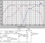
I was considering that (despite Sreten's valuable comment) a 2kHz tweeter xo was 'too low' in your case?
However ,see the attached. Its still '1st order on the mid' , no Zobels, and looks quite acceptable. What do you think? The Tweeter xo is around 2100 Hz , but it seems too low? As far as Q's go, as yet I have no idea,...so I don't know what the resultant 2nd-order-name is yet, lol.
(and of course Sretens comments apply) Sreten, could you help me out here please? grant
Please feel free to correct me on anything if I'm wrong! (and there could be plenty of opportunities for that, lol!)
I was considering that (despite Sreten's valuable comment) a 2kHz tweeter xo was 'too low' in your case?
However ,see the attached. Its still '1st order on the mid' , no Zobels, and looks quite acceptable. What do you think? The Tweeter xo is around 2100 Hz , but it seems too low? As far as Q's go, as yet I have no idea,...so I don't know what the resultant 2nd-order-name is yet, lol.
(and of course Sretens comments apply) Sreten, could you help me out here please? grant
Attachments
Hi, to anyone,
I might say my latest graph looks great to 6kHz, could this be true? Please consider it and reply, thanks, grant
I might say my latest graph looks great to 6kHz, could this be true? Please consider it and reply, thanks, grant
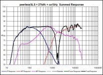
Grant, here's a graph of your latest figures put into the sim program I'm working in.................Pretty weird stuff....I can't figure it out.........Almost identical driver response curves per each driver, but the summed response is totally different................Respectfully.....Omni
Attachments
Hi,
the second graph indicates I presume relative reversed tweeter polarity.
Both of them indicate the CA15RCY is in a large box for a mid.
I'm not sure that the mids actual Fb and Qb are correct.
The graphs do show the relatively broad overlap of simple crossovers.
It fairly pointless tweaking the on-axis response to perfection.
The next thing to do is use 30 degree off axis responses and
recalculate drivers offsets for 30 degrees and rerun the sim for
vertical +/- 30 degrees.
If this looks good, also look at 30 horizontal (normal offsets).
The average of all three is more important than the first being flat.
🙂/sreten.
Sreten, Thank You for your reply............I used the same component values as Grant did and kept the polarity of all speakers the same as Grants schematic above in his post so everything is identical, except, of course, the summed response, Unless I did something wrong, however, I will double check it................Here's the story with the Midbass and my cabinet; Driver: SEAS CA15RLY, According to Vance Dickasons dissertation on mid cabinets, He recommends a non-parallel sided box. Did that. He recommends a box frequency of at least 2 octaves below crossover point. 300 Hz crossover point would yield a box frequency of 75Hz. Through intensive research through several sources, I found that a .5 Qtc was desirable or in that area {critically damped}.........So here's what I did, and what I have: I modelled the CA15RLY in WinISD using manufactures data, as well as Zaphs TS measurments, in addition to the data base in WinISD, so I used 3 sources to do various models. I came up with a 15 liter box rendering a box frequency of 73.3 Hz on average. The Qtc is in the range of .517 to .53. So it appears 15 liters meets the afformentioned criteria, so I designed and built the midbass cabinet to be 15 Liters, sealed, and expect for a Qtc in the low to mid .5's.................Here's the weird thing man.........Grant and I used the same FRD and ZMA files to do our models..............Beats the **** out of me.............I hope this information can be useful........................Respectfully..........Omni
Omni, I think yours and Grants last sim looks very much alike, looking at driver slopes - only yours actually show the phase problem which ought to be there, looking at slopes between mid and tweeter
To me it seems you are close, but it needs a bit adjustment - upper crossoverpoint is too low
To me it seems you are close, but it needs a bit adjustment - upper crossoverpoint is too low
omni said:...............Here's the story with the Midbass and my cabinet; Driver: SEAS CA15RLY, According to Vance Dickasons dissertation on mid cabinets, He recommends a non-parallel sided box. Did that. He recommends a box frequency of at least 2 octaves below crossover point. 300 Hz crossover point would yield a box frequency of 75Hz. Through intensive research through several sources, I found that a .5 Qtc was desirable or in that area {critically damped}.........So here's what I did, and what I have: I modelled the CA15RLY in WinISD using manufactures data, as well as Zaphs TS measurments, in addition to the data base in WinISD, so I used 3 sources to do various models. I came up with a 15 liter box rendering a box frequency of 73.3 Hz on average. The Qtc is in the range of .517 to .53. So it appears 15 liters meets the afformentioned criteria, so I designed and built the midbass cabinet to be 15 Liters, sealed, and expect for a Qtc in the low to mid .5's.................
Hmmm........
so you end up with a midrange volume higher than most would use for using the driver for bass also.
Its what you get for taking technical wafffle too seriously and too literally.
I wouldn't call it extensive "research", I'd call it extensive "misinformation".
Sadly all too easy to find once you start looking for it.
🙂/sreten.
Attachments
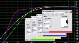
Sreten, Thank you for taking the time to model the CA in WinISD. It definately shows different response curves for the given volumes.........1 : Being that I am using it as a midbass for my bandpass at 300Hz and above; Is the response below 300 important to my scenario, being that all four graphs converge to identical responses at 300Hz and above ? And if so, How?....2: I am astounded that sources such as Vance Dickason, Dick Olsher, and Lynn Olson may be considered misinformers.....Maybe it's my naivete....I don't know, man, I have studied their works extensively and they all have solid reputations.......3 : Is a .5Q box NOT advisable for a midbass in the 300Hz to 3000 Hz range ?....and if so, are you recommending the values on the graph you posted OR do you have a different recommendation ? 4 : That fact that the midbass cabinet is currently 15 Liters does not preclude the idea that I have the option of making it smaller, which was one of my considerations when I designed it. If so, what volume would you choose, bearing in mind that it's a sealed cabinet? Like I said before, I am grateful of the time and interest you have put into Grants' and my project, and I look forward to your continued input and support.................Tinitus, Hey man, I have been playing with your resistor on parallel components concept, and have gotten some neat preliminary stuff......Heres the deal,..... and my observations. I put a 2 ohm resistor in series with the shunt capacitor on the highpass section of the midbass, and it seemed to "round out" the response curve, shaping it into a smooth, rounded curve, almost completely tracing over my target curve. { Bessel Alignment is the Target Alignment I have chosen }. That seems like pretty cool stuff.............Is this "rounding out", so to speak, the desirable phenomenon you have been advocating..........Unfortunately, I haven't had the time to really sink my teeth into this, however, it's slowly in the works.........Grant, this crossover simulation stuff has been quite absorbing, and the amount of work you have put in is quite respectable...........I'll bet that by the time you get your boxes done, they will sound incredible..........At any rate, I gotta get back to yhe sims............................Respectfully...........Omni
- Status
- Not open for further replies.
- Home
- Loudspeakers
- Multi-Way
- 3way XO help greatly appreciated!