Hi Sreten,
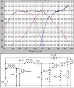
firstly re the tweeter Rzobel (was 2 ohms) being too small, I increased it to 9 ohms, (just as a guess as I don't have time at the moment to
'work the theory' unfortunately!), here's the new chart&circuit.
(I haven't changed any other values, just wanted to model only 1 value at a time).
The only real difference I can see is that the 13?kHz tweeter peak is now 2dB higher with 9 ohms. This is why I specified 2 ohms.
Any comments appreciated, thanks grant
Attachments
Sreten,
the 60 ohm lpad R on the mid makes so little difference it would be inauble, but the response looks a teeny bit nicer, lol. thank you grant
the 60 ohm lpad R on the mid makes so little difference it would be inauble, but the response looks a teeny bit nicer, lol. thank you grant
Sreten! help!, lol
What I don't understand is this:
firstly, with no tweeter Zobel the tweeter response is err, yuck!
A 2 ohm tweeter Rzobel has a lower peak(2 db) than 9 ohms.
So I thought what would happen if I removed the resistor?
The response looks the best yet! How could this be so? thanks grant
(see attached)
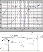
What I don't understand is this:
firstly, with no tweeter Zobel the tweeter response is err, yuck!
A 2 ohm tweeter Rzobel has a lower peak(2 db) than 9 ohms.
So I thought what would happen if I removed the resistor?
The response looks the best yet! How could this be so? thanks grant
(see attached)
Attachments
Hi,
Ok, you have discovered the amplifier melting capacitive voltage divider.
It works like an L-pad except overall impedance plummets with frequency.
Go back to a standard L-pad, and keep an eye on overall impedance.
🙂/sreten.
Ok, you have discovered the amplifier melting capacitive voltage divider.
It works like an L-pad except overall impedance plummets with frequency.
Go back to a standard L-pad, and keep an eye on overall impedance.
🙂/sreten.
Hi Sreten, (grant again....lol)
I'm hoping you may be able to 'set me right' on many of the points you raised, if you have the time? Hope so! Because you replied, thanks!
( I have lots of questions - it could take quite a while!) New concepts for me unfortunately take a little longer nowadays, lol my situation reminds me of the Jethro Tull album I bought 30? years ago titled 'Thick as a Brick'! haha..... Anyway... Regarding:
1) your quote: "2nd order electrical parallel c/o's generally will not need zobels." *Q*: I'm wondering why my latest '2nd' xo response in SW requires Zobel on tweeter for best response?
2) my question about less attenuation near Fs=higher distortion and your method to model model tweeter in WinISD. How do you achieve this? Please correct me if I'm wrong, but all the driver
database models are for woofers? No specified Vifa or Seas tweeters? And how is it done please?
3) mixing parallel and series in the total network. Unfortunately I think this is beyond me! Would there be any real benefits to be gained over a 'full parallel 2nd order'? Schematically I'm still trying to visualise the overall circuit (and understand series xo's!)
Also, do you think that my latest xo i.e. '1st on Mid' (excluding incorrect tweeter Zobel/LPad) is a legitimate design?
4) now to my total confusion, I'm STILL trying to figure 'your reply' out re distortion and filter 'order';
your quote: (format edited, 'a to e' points inserted for reference):
"(simplified somewhat)
a/ Consider a tweeter with a required crossover that you get the response you want with a 1st order electrical crossover at 4khz.
b/ Excursion increases 12dB per octave you go down, with 6dB c/o it is still increasing at 6dB octave so will be 12 dB higher at 1khz than 4khz.
c/ But this is forgetting the Fs of the tweeter. Response below Fs of the tweeter rolls off at 12dB octave matching the increase.
d/ So the excursion of the tweeter levels at Fs of the tweeter, and falls 6dB octave below Fs (18dB per octave amplitude response).
e/ Given the first paragraph the higher the Fs of the tweeter, the more juice can be applied, but also note the higher the Fs the higher the actual acoustic response becomes 3rd order."
MY QUESTIONS (regarding your comments):
Re: a/ ....Ok , No problem ;
b/ I'm quite confused now ;
c/ first part seems ok, but still otherwise lost with (b/) ;
d/ sorry I don't understand how this can be, I guess it all 'hinges' on b/?
e/ about more juice, higher Fs and 3rd order......WHAT? Sorry, I've completely and totally lost it!
*Sreten, could you please elaborate on all this so that I may have some chance to conceptualize what you are trying to relate to me?*
As I said earlier, I need to understand this! From my point of view, certainly your time won't be wasted. Thanks a lot, and most sincere seasons greetings!, grant
(ps: you have kindly offered these observations, (from great experience), so I also hope you might kindly like to clarify, addressing my 'beginners viewpoint' questions, as dumb as they may be!.....
Grant,
Tweeter ZOBEL.....thats very good, now you have proved it makes sense....... try 2.7-3.9 ohm
Omni,
Resistor on paralel component is in series with the component, just like a zobel ..... R/C.... what it is called when done on inductors I really dont know ....I/R(?).... I like to call it dampening resistor
Personally, without those resistors I get either harsh sound or phase problems, I have tried without
But the resistor might demand for a different values on "C" or "I"
I have been experimenting to find a "formula" for these resistor, and it seems that around or just above drivers DC(ohm) is a sensible value
The resistor opens the possibility to use a slightly bigger parallel "C" and smaller parallel "I", which is then "turned down" by the resistor, making it act more "softly", and the result is a more "round" slope - soft curve, soft sound
At the same time it has influence on the "Q" of the curcuit, and you might say that it takes away some "ringing" and ressonance - but that might be hard to see on simms or measurements
I DONT claim that the resistors has to be there, but personally I cant make it work without .....my friends say that my speakers are about as good as it gets, thats good enough for me
BTW.... I think even ZAPH has said that he cant make the speakers he does, without listening, neither sims or measurements does it on its own - and I think this proves that its not easy at all, even with the best tools, It takes time !
Thank you very much ..Sreten, most appreciated...
*This is my initial reply*....but its maybe inappropriate?* So, I'll need to reconsider it and get back to you, yet again!, lol
Re: "amplifier melting capacitive voltage divider." From your comment it seems maybe this would apply to a tweeter Zobel with much? less power applied than a mid or woofer? Sorry, I don't know, is overall power 'the issue here' (by virtue of incorrect tweeter Zobel) delivered in relation to the tweeter? Certainly don't want to blow up the amp! I assume that no Zobel would be more protective to the amp than a poorly designed one? I could understand for a woofer, of course, but a tweeter 'power-wise' intrigues me, and of course I may have missed the point.
Re: "It works like an L-pad except overall impedance plummets with frequency.
Go back to a standard L-pad, and keep an eye on overall impedance."
OK , thanks! So, if I understand what you're saying, the impedance presented to the amp, is more important than 'nice screen graphs' - which makes sense of course! And I definitely will from now on place more importance on impedance graphs! If any graph goes below say 4 ohms overall then I 'spose there is a problem!
*thank you very much*! I hope I have understood you correctly and communicated my reply in an understandable way. grant
I may comment that all new tweeters form ScanSpeak or Vifa are 3ohm DC ( 4 ohm nom)
Omni,
When I said that "dampening" resistor in series with parallel components should be around or just above driver impedance - I was referring to driver DC impedance
Omni,
When I said that "dampening" resistor in series with parallel components should be around or just above driver impedance - I was referring to driver DC impedance
Hi GN,
If you do not understand that :
For a driver operating is a flat region of response the level of
excursion quadruples every octave you go down, or quarters
every octave you go up. (increases / decreases 12dB).
Then you will struggle with what I'm saying.
Take a normal tweeter, its bass response rolls off at 12dB/oct.
Given constant voltage drive its excursion is also constant in this region.
(this is also true of a sealed box bass driver, so its quite easy
to model the excursion behaviour of tweeters with bass drivers)
The acoustic response of a driver has to be falling at more than
12dB/octave for excursion to reduce as you go down in frequency.
This is why ribbons and professional tweeters always say 18dB/oct minimum.
Say the Tweeters Fs is 1k and c/o point is 4k.
if you want excursion to decrease going from 4k to 1k you need a
3rd order crossover.
Or take the ubiquitous audax cheapo tweeter types :
http://www.partsexpress.com/pe/showdetl.cfm?&Partnumber=276-020
These types are commonly used with only a series capacitor.
Fs is always around 3kHz, sounds bad compared to a good domes
500hz to 1kHz, but if it wasn't 3khz, with simple crossovers they
would simply overload due to excursion limitations.
They work because with a series capacitor the acoustic response
is always going to be 3rd order with 2 orders at 3khz, consequently
for constant voltage drive excursion will fall below 3khz at 6dB/oct.
🙂/sreten.
If you do not understand that :
For a driver operating is a flat region of response the level of
excursion quadruples every octave you go down, or quarters
every octave you go up. (increases / decreases 12dB).
Then you will struggle with what I'm saying.
Take a normal tweeter, its bass response rolls off at 12dB/oct.
Given constant voltage drive its excursion is also constant in this region.
(this is also true of a sealed box bass driver, so its quite easy
to model the excursion behaviour of tweeters with bass drivers)
The acoustic response of a driver has to be falling at more than
12dB/octave for excursion to reduce as you go down in frequency.
This is why ribbons and professional tweeters always say 18dB/oct minimum.
Say the Tweeters Fs is 1k and c/o point is 4k.
if you want excursion to decrease going from 4k to 1k you need a
3rd order crossover.
Or take the ubiquitous audax cheapo tweeter types :
An externally hosted image should be here but it was not working when we last tested it.
http://www.partsexpress.com/pe/showdetl.cfm?&Partnumber=276-020
These types are commonly used with only a series capacitor.
Fs is always around 3kHz, sounds bad compared to a good domes
500hz to 1kHz, but if it wasn't 3khz, with simple crossovers they
would simply overload due to excursion limitations.
They work because with a series capacitor the acoustic response
is always going to be 3rd order with 2 orders at 3khz, consequently
for constant voltage drive excursion will fall below 3khz at 6dB/oct.
🙂/sreten.
tinitus said:Grant,
Tweeter ZOBEL.....thats very good, now you have proved it makes sense....... try 2.7-3.9 ohm
[/B]
Hi,
Case not remotely proven, other than he'd be rather good at blowing up amplifiers.
🙂/sreten.
Nice explanation
And like I have mentioned, your 2khz is too low - it will probably sound harsh and distorted
A good mid is much better at reproducing high frequencies, than a tweeter is at reproducing midrange
And like I have mentioned, your 2khz is too low - it will probably sound harsh and distorted
A good mid is much better at reproducing high frequencies, than a tweeter is at reproducing midrange
grantnsw said:
The response looks the best yet! How could this be so? thanks grant
(see attached)
Hi,
look at the (lack of) impedance at high frequencies for this case.
You've modelled a highly impractical capacitor L-pad.
🙂/sreten.
tinitus said:
And like I have mentioned, your 2khz is too low - it will probably sound harsh and distorted
Hi, I checked that, according to Zaph 2khz / 2nd order should be fine, 🙂/sreten.
Tinitus, thanks! I'll look into it, very much appreciated and thank you for your very considered response! All the very best wishes to you for the 'festive season' . I have some questions, but its late here, may I ask you later? many thanks, grant
Yah, ofcourse it works, I simply just like the sound with a high crossoverpoint.... smaller components/less phase problems ? .... others would probably prefer it much lower
It is my belief that to get a coherent speaker, bas should play midrange too, and midrange should reproduce some high frequencies
Ofcourse, you may ask all you want, and will TRY to answer - Sreten is very good at explaining the theory - I am more like a working man with a much differnt approach, and sometimes make my own conclusions, and they work for me, but ofcourse that dont mean they will work fore everybody
But you have a nice tool, keep experimenting 😎
Grant.......You mad scientist,you.............You have been working like a beaver on these sims, and it appears you are settled on the woofer 8.6mH coil and between 70-75uF on the cap. I agree with that particular rolloff. I think Tinitus mentioned that it looked like a good rolloff and then to simulate the other drivers to the same shape... So it seems like woofer, for now is cool...........Tinitus, I have studied your comments closely and have a similar philosophy, however, less experience. I deeply appreciate your analysis and encouraging thoughts. In one of your posts you said "fact is, you are actually close". Were you referring to the woofer rolloff? After reading your ideas on the series resistors I hope I know what direction to take.....It appears the midbass IS the biggest problem, as also exemplified by Grants' sims................Grant, as far as tweeter crossover points are concerned, it has always been my thought that Xover for tweeter should fall at least 2 octaves above Fs. Though a lower crossover point may create a louder sounding upper end, and appear to create a summed response curve that looks good, I think a bit higher crossover point will remove unwanted resonances and curtail "ringing" in the response, lending itself to a faster, more transient response, and sound cleaner. It would also greatly protect the tweeter from harshness and potential damage. This then puts the onus on the crossover design to deal with the midrange, which seems to be the challenge..........Grant I also saw your sim utilizing the components I used in mine, and though there are similarities in our graphs, there are also major differences. Your midrange curve appears steeper on both ends than mine. This is curious, and I am wondering if this is a function of the programs we are using..................Not sure here. Also, your crossover points appear alot different as well. Yours are higher on the low end of the xover, and lower on the high end of the xover. Again, I am not sure why. Are you using 300-3000 Hz crossover points? Anyway, I will keep simming as I learn more from all of you......... I am deeply moved by the fellowship that has developed on this thread, and that includes EVERYONE who has shared here. I am grateful to be part of it....Respectfully..........Omni...............PS a few of lifes' twists have occurred, which has delayed new sim charts, which will be forthcoming this weekend.....................Warm Regards to you all 🙂
Hi Sreten,
I truly deserve the 'DIY Dunce of the Year Award'! That deleting Rzobel idea was utter madness, the amplifier would have been short circuit. I wish I had taken a little time to think about the dire
consequence before I had posted it! This was my most serious blunder, I'll try to be more wise next time before I post total rubbish! <embarrassed> grant
(also I think it would be possible to model tweeters in WinISD)
Hi Sreten,
Thank you very much for your detailed analysis of tweeter excursion and the Audax example. I'm going over and over the points you make. I really hope the 'penny drops' soon! grant (struggling)
Thank you very much for your detailed analysis of tweeter excursion and the Audax example. I'm going over and over the points you make. I really hope the 'penny drops' soon! grant (struggling)
Right!
You are on to something, that you are working with different programs might give you different results.... makes me think....
You havent commented on my question how you handle drivers offset values in your sims, could be important
I would think if they are phase aligned correctly on baffle, offset values would be set to ZERO in your program, or... entlighten me please???
But the fact that there are different opinions about correct phase alignment ..... I would think it is important to know the reference of the specific program
Hi Omni,
From memory the 27TDFC resonance is 550Hz. Also from memory, in an earlier post, for my 'full 2nd order electrical' circuit, the tweeter and mid 'appeared' to (from the summed graph) crossover at 2kHz. For a 2 octave separation this would give obviously 2200Hz xo. But if I remember correctly, lol, I might have onset Alzheimers!, I think the LC products for that version's tweeter HP and mid LP were in fact both at 3kHz?, but 'you' could never tell from the graph without calculating it?
Also, while my '1st order electrical on the mid' err, 'design' - lol!, looks great 'on screen', that is the response looks nearly identical to the 2nd order one, there could be other audible factors that may need to be considered, that is the 'slopes' may not be complementary and possibly cause audible interference/intermodulation?. (This might only be confirmed by trying it out?). Besides I made a HUGE Zobel *goof-up*! And my LPads were 'suss' as well! So , given this, I hope it helps somewhat, grant
- Status
- Not open for further replies.
- Home
- Loudspeakers
- Multi-Way
- 3way XO help greatly appreciated!