Hello everyone!
*SRETEN*, may I ask a couple of naiive (ill-informed?) questions please?
Firstly, If a transistor amp with 8 ohm output is operated with an xo with a minimum impedance of 4 ohms, I presume the amp would 'cook'? If the same amp also has a 4 ohm output, I presume it
would be ok? ...I'm pretty vague on this stuff nowadays. ( also would the output-stage coupling method make a difference?)
Also, is it possible to calculate the 'effective resonance' of a 4th order electrical filter? If so, would you have a reference to a formula? thanks ...(no 'google joy' as yet)
*OMNI*, I couldn't help myself! I just had to try to achieve an xo that better met your design goals.
The latest circuit (attached) would need to be considered vis-a-vis Sreten's off-axis modeling procedure.
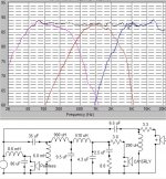
Anyway, its now '4th order electrical' on the CA LP; the steeper rolloff now looks like it may be (xo-point on LP) at 2500-3000? ( I don't as yet have a resonance formula for a 4th order). There is also an oddly valued (but seemingly effective) Zobel on the CA.
*I do hope it won't blow up your amp!*
The Zobel values look good because they eliminated a new nasty CA peak at about 4500Hz - other values didn't!
Minimum overall impedance does not drop below 4.2 ohms at 4800Hz. (maximum impedance is a whopping 147 ohms at 25HZ!) The CA peak/dip seems to be nicely smoothed and the response is now +- 1.5 dB from 50 to about 18kHz, - not too bad? Without those particular Zobel values, I could not get a smooth response - I truly hope they are valid.
So, superficially, it seems that your design requirements are now met? The CA's values were chosen purely by trial and error, they were the best I could get this way. Unfortunately there's 4 more components than the last 'full 2nd-order' I emailed you.
The CA's FRD data showed it was still at 86 dB at nearly 12kHz!, so that's why I thought a 4th order would be beneficial wrt your requirements. Of course, in this respect the CA response looks vastly improved over my earlier '1st on mid' design. Also, please note the inverted woofer.
I'm very interested to hear anyones comments on it. I think I might finally be getting somewhere OR is it puerile rubbish ( that is, fundamentally flawed)?
Many thanks to you both, and Tinitus!.........grant
*SRETEN*, may I ask a couple of naiive (ill-informed?) questions please?
Firstly, If a transistor amp with 8 ohm output is operated with an xo with a minimum impedance of 4 ohms, I presume the amp would 'cook'? If the same amp also has a 4 ohm output, I presume it
would be ok? ...I'm pretty vague on this stuff nowadays. ( also would the output-stage coupling method make a difference?)
Also, is it possible to calculate the 'effective resonance' of a 4th order electrical filter? If so, would you have a reference to a formula? thanks ...(no 'google joy' as yet)
*OMNI*, I couldn't help myself! I just had to try to achieve an xo that better met your design goals.
The latest circuit (attached) would need to be considered vis-a-vis Sreten's off-axis modeling procedure.
Anyway, its now '4th order electrical' on the CA LP; the steeper rolloff now looks like it may be (xo-point on LP) at 2500-3000? ( I don't as yet have a resonance formula for a 4th order). There is also an oddly valued (but seemingly effective) Zobel on the CA.
*I do hope it won't blow up your amp!*
The Zobel values look good because they eliminated a new nasty CA peak at about 4500Hz - other values didn't!
Minimum overall impedance does not drop below 4.2 ohms at 4800Hz. (maximum impedance is a whopping 147 ohms at 25HZ!) The CA peak/dip seems to be nicely smoothed and the response is now +- 1.5 dB from 50 to about 18kHz, - not too bad? Without those particular Zobel values, I could not get a smooth response - I truly hope they are valid.
So, superficially, it seems that your design requirements are now met? The CA's values were chosen purely by trial and error, they were the best I could get this way. Unfortunately there's 4 more components than the last 'full 2nd-order' I emailed you.
The CA's FRD data showed it was still at 86 dB at nearly 12kHz!, so that's why I thought a 4th order would be beneficial wrt your requirements. Of course, in this respect the CA response looks vastly improved over my earlier '1st on mid' design. Also, please note the inverted woofer.
I'm very interested to hear anyones comments on it. I think I might finally be getting somewhere OR is it puerile rubbish ( that is, fundamentally flawed)?
Many thanks to you both, and Tinitus!.........grant
Attachments
Err, a Jpeg compression error caused the loss of the link from the
Zobel to the CA '4th order'? Anyway, it is there!
Zobel to the CA '4th order'? Anyway, it is there!
Omni,
I forgot to mention that there still seems to be a 'nice symmetry' about the rolloff curves, and that the tweeter seems to be 'well protected' at resonance, so hopefully low distortion, and also because of the steep CA rolloff.
The 1 dB Peerless peak at 80Hz? should be of no concern, its too small to worry about, imho. Also, imho, trying to eliminate it, would be very costly indeed. Are there other issues which I may not have addressed yet? I did try various Zobels on the woofer, but they didn't seem to provide any useful benefit. thanks, grant
omni said:
1)And if so, How?....2: I am astounded that sources such as Vance Dickason, Dick Olsher, and Lynn Olson may be considered misinformers.....Maybe it's my naivete....I don't know, man, I have studied their works extensively and they all have solid reputations.......3 : Is a .5Q box NOT advisable for a midbass in the 300Hz to 3000 Hz range ?.
2) If so, what volume would you choose, bearing in mind that it's a sealed cabinet? Like I said before, I am grateful of the time and interest you have put into Grants' and my project, and I look forward to your continued input and support........
3)........Tinitus, Hey man, I have been playing with your resistor on parallel components concept, and have gotten some neat preliminary stuff.....
.
Hi,
1) whats pragmatic and practical doesn't math up to ideal theory.
how many people have sattelites with Fb = 20Hz, Qb = 0.5 and
cross them over at 80Hz to a subwoofer ? doesn't make sense....
2) Around 5 litres probably, unless i had a good reason not to.
3) For second order crossovers the effect is similar to varying
the ratio of Cand L, i.e. similar to reducing the Q of the filter.
🙂/sreten.
grantnsw said:Hello everyone!
*SRETEN*, may I ask a couple of naiive (ill-informed?) questions please?
Firstly, If a transistor amp with 8 ohm output is operated with an xo with a minimum impedance of 4 ohms, I presume the amp would 'cook'? If the same amp also has a 4 ohm output, I presume it
would be ok? ...I'm pretty vague on this stuff nowadays. ( also would the output-stage coupling method make a difference?)
Also, is it possible to calculate the 'effective resonance' of a 4th order electrical filter? If so, would you have a reference to a formula? thanks ...(no 'google joy' as yet)
1) possibly - high phase angles + low impedance are the real amplifier killers.
2)
Higher order filters conform generally to alignments - e.g.
Bessel, Linkwitz/Riley, Butterworth, equiripple Chebyshev, etc....
for 2 order filters each of the above = a Q value. Chebyshev
= a range of Q's as it has a range of ripples = Q > 0.7.
Higher order filters are treated as cascaded 2nd order filters.
If the filter is odd you add a cascaded first order filter.
eg. first order + 2nd order Q=1 = 3rd order Butterworth.
Two cascaded 2nd order Butterworths (Q=0.7) = 4th order L/R.
Phase response and group delay (effective resonance) of
high order filters is always much worse than simple filters.
🙂/sreten.
Hi Sreten, thanks for your reply,
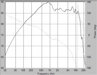
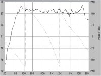
Re: 1) ...high phase angles. The attached shows the phase for my last circuit. Does it look ok to you? That is, is the abrupt +- 180deg phase shift, a concern? Or is it desirable? I assume it's ideal, but
I really have no idea!
Re: 2)..Yes, thanks, I realise that LR4 are in effect 2 cascaded Butterworth-2's. But would you kindly explain this please? quote: ( *my emphasis*! )
"Phase response and group delay (effective resonance) of high order filters is always MUCH WORSE than simple filters".
...What does this infer please?
I had just assumed!, lol, that an (overall) 4th order filter resonance was an (unknown to me) mathematical formula for the individual cascaded sections? But of course, I need to re-read about group delay ( I still haven't quite understood it yet, together with many other concepts!) Many thanks , grant
Oops, Btw, the CA Zobel should have been 'on/across the driver'!.....
Attachments
Sreten, I forgot to ask!
Would you please help me out here? Another 'thing' I would like to know!
Given your recommended (qualified) CA closed enclosure size of possibly 5 Litres (seems entirely reasonable to me, but I'm not really savvy with WinISD!) ... My question is this:
Would it make ANY audibly discernable difference, given my last xo? *Assuming* that xo is valid, then, the CA is almost 20dB down at 200Hz. So, I guess, if the response is so far down, then, what
difference would it make? I dunno. Maybe, there are, as always, other issues?....thanks grant
(I'm just trying .still. to get all of this into perspective)
Hi Omni.
This is very interesting! I HAD believed that the Zobel MUST be the last 'component' across the driver, so that is what prompted my last 'errata'. But, just now, I put the CA 3 ohm resistor, BEFORE the Zobel
and got a 2dB? peak! So, maybe my original version was 'better'? (according to SW) ....FWIW!
( I'm not sure if this would apply to a correctly designed LPad?, which might 'stabilise' impedance?)
Anyway, do you think this design is worth pursuing?, grant (all comments from anyone most welcome!)
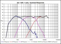
Hey guys, I have been simming and simming, trying for the simplest xover, been incorporating series resistors on shunt components, and here is the latest graph. Check it out. New crossover points..............but not straying too far off my original goals...............Has some advantages, I think.........Any input is greatly appreciated...........Respectfully.......Omni............If it needs some tweaking, any constructive critique is welcome.......Minimum impedance is 4.58 Ohms...........Too low? or OK impedance wise............Omni
Attachments
Omni,
It looks great to me! The CA seems nicely controlled too. Would you kindly put your circuit here for interest? thanks , grant
It looks great to me! The CA seems nicely controlled too. Would you kindly put your circuit here for interest? thanks , grant
Sreten, please, I'm still wondering!
If a speaker is 4 ohms minimum impedance, and the phase looks like the abrupt change between drivers +- 180 deg (in my last example) then would it 'cook' an 8 ohm output amp? I don't want to blow up amps! Of course! So, if you could give a definitive answer on this it would be most appreciated. grant
If a speaker is 4 ohms minimum impedance, and the phase looks like the abrupt change between drivers +- 180 deg (in my last example) then would it 'cook' an 8 ohm output amp? I don't want to blow up amps! Of course! So, if you could give a definitive answer on this it would be most appreciated. grant
Hi,
shunt resistor - I place them on negative, like you have done
Looking at your crossover makes me speculate....
I wonder why you have to reverse tweeter polarity ..... maybe some values are just a tiny little bit off .... making you reverse polarity
I dont like those big series resistors on mid and tweeter
And I still dont understand why people tend to use such big
Inductors on MIDS
And that big inductor on BASS might eat too much sensitivity from the midbass range and the whole speaker as such
I have always learned to reverse midrange polarity only, but ofcourse I could be wrong....in all of it 🙂
Tinitus,........ Big series resistors on mid and tweet: Neither do I..... Seems that they may really lower SPL...............in combination with the amount of juice the 10mH inductor is gonna draw........Big inductor on mid: Somewhere I read {not sure where} that the large inductor on mid has a tendency to stifle the sound of the driver........Weird how it produced a relatively smooth summed response................At any rate, to quote Grant "back to the drawing board"......Seems as though I am learning a little bit as we move along in this endeavor......Oh Well...........Thank You very much for your candor...............Respectfully.......Omni..............Polarity of tweeter issue....I don't even know what to say..............
grantnsw said:Hi Sreten, thanks for your reply,
Re: 1) ...high phase angles. The attached shows the phase for my last circuit. Does it look ok to you? That is, is the abrupt +- 180deg phase shift, a concern? Or is it desirable? I assume it's ideal, but
I really have no idea!
The phase changes are not abrupt at all, its the way its graphed.
However you have shown the acoustic phase, the issue is the electrical phase.
grantnsw said:
Re: 2)..Yes, thanks, I realise that LR4 are in effect 2 cascaded Butterworth-2's. But would you kindly explain this please? quote: ( *my emphasis*! )
"Phase response and group delay (effective resonance) of high order filters is always MUCH WORSE than simple filters".
...What does this infer please?
I had just assumed!, lol, that an (overall) 4th order filter resonance was an (unknown to me) mathematical formula for the individual cascaded sections? But of course, I need to re-read about group delay ( I still haven't quite understood it yet, together with many other concepts!) Many thanks , grant
To compare 2nd order and 4th order filter characteristics look
at the behaviour of sealed boxes versus vented boxes.
consider phase response :
1st order = 90 degrees stopband
2nd order = 180 degrees stopband
3rd order = 270 degrees stopband
4th order = 360 degrees stopband
etc.....
The higher the order, the more phase change you get, the "worse"
the transient response becomes - away from the "ideal" behaviour.
🙂/sreten.
Hi,
4th order electrical on the mid doesn't seem a good idea to me.
My starting point for the crossover would be the following :
No zobels ......................
First order series between the bass and mid unit.
Second order parallel for the mid and L-padded tweeter.
So 1st order low pass, second order high pass on the mid.
It seems a parallel LCR circuit in series with the mid may be needed
to control the rather large peak around 1Khz, after getting this near
then consider any other other series resistance for level setting.
If the first order series bass / mid will not work only then consider
2nd order parallel for this c/o point.
Question :
What is the difference between a 1st order electrical parallel high pass (inductor in series) with
driver zobels Cz and Rz and a 2nd order electrical parallel high pass filter with no Zobel components ?
Answer ?
🙂/sreten.
Hi everyone,
Your responses here are truly insightful, fun and interesting!
Thanks, particularly to you Sreten for answering my uneducated questions. I'll need to carefully, (as best I can) consider everything and hopefully post some 'meaningful' replies, asap.
Sreten, (briefly)
I do like/appreciate you notion of a LCR trap for the CA, it seems appropriate to me (qualified as usual!)
Also, I'm very interested in your suggested combination of series and parallel filters. Would it be ok to ask you to post a 'raw' schematic of this scenario, that is, in general terms only (no component values) of what your suggested network would look like? So that I might be able to further research it? The only 'series' link I've found so far is Graddon, I think, maybe also Elliot? I'm still very much lacking on series theory. Many thanks, grant
- Status
- Not open for further replies.
- Home
- Loudspeakers
- Multi-Way
- 3way XO help greatly appreciated!