[TL;DR - I built a PPP 3E29 amp with 5687 drivers. It works. I used toroidal power transformers as OPTs. It sounds good. I made lots of graphs and posted them.]
This is my first post to the forum, though I have been lurking for a while reading many interesting posts. I don’t have a background in electronics (I was a CS major) though I have a solid understanding of physics. A few years ago I built a single ended EL84 guitar amp kit for my daughter. At the same time I was experimenting with 630m radio beacons and needed a 100W RF amplifier for my experiments. I ended up building a dual 807 power amplifier based on a design from ARRL.
Fast forward to a few months ago. I had thought it would be fun to reuse some of my old RF amp components in an audio amp one day. Back in November I saw a design by triodedick for an 807SE amplifier that had been built by Mark of Blueglow Electronics. Watching his YouTube videos gave me the impetus to build one for myself. It’s still in breadboard form and may or may not make it to a chassis one day, but it was a fun project.
For my second amplifier I wanted to have a go at designing something from scratch. I realize that there’s nothing new under the sun, so by “from scratch” I mean picking the tubes, basic architecture and operating points rather than building or modifying an existing schematic. Not surprisingly, what I ended up with looks very similar to other designs out there. For the preamp/drivers I had bought some 5687 tubes from Parts Connexion during one of previous orders. They were on sale for $4.50 each and there weren’t many designs out there using them. This was good since I wanted to experiment for myself. I prototyped a few pre-amps and even a 1W SE design. Around the same time I had seen 829B/3E29 tubes and thought it might be fun to build a push pull amp. Posts seemed to suggest it had been done, but I didn’t find much in the way of designs (a good thing again.) Once I had the work underway I did find a few posts on GU29 PPP amps that gave me confidence it could work.
For the design I started by driving the 3E29 from a signal generator in class A mode to get the power supply built – screen, grid voltages, etc. I decided to go with a cathodyne phase splitter since I liked the simplicity. I found I needed two pre amp stages in order to get adequate gain – the 5687 tube being only medium mu. I will probably experiment with a 12AX7 at some point since I expect only to need one stage in the preamp. The first version was a single tube, push pull amp using a pair of Hammond 125ESE single ended OPTs wired together to make a PP OPT. I like these OPTs since they have taps for 2.5K, 5K and 10K impedance. I started with the 5K taps on each and then when I added the second 3E29 I moved to the 2.5K taps.
When I found posts on GU29 PPP amps I ran into people using toroidal power transformers as PP OPTs. Specifically, a dual voltage (115/230V) 9V transformer can be used as a 5K PP OPT by wiring the two primaries in series, and feeding the B+ voltage in the middle. I found an Antek transformer (AS-1209) for about $20 that I thought would be fun to try. I read posts about core saturation and DC currents and you’ll see I did a couple of experiments to see how much DC balance affected performance.
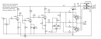
I’m posting the schematic of the amp – I have built both channels and am listening to it through Klipsch RP-160M speakers. It sounds good to me with nice bass response. Not that I’m an audio expert. I have been using the Digilent 2 PC oscilloscope with the free Audio Analyzer suite from “The Stuff Made” to analyze the amp. I’m including some stats and graphs that I made using the setup. I have tried idle plate currents in the 3E29 ranging from 10 to 30 mA per section at 425V. Here are some THD+N measurements made at 1KHz:
Bias Iplate THD+N@1W PWR@1%THD+N MaxPWR
-19V__10mA____0.29%_____37W______44W
-18V__15mA____0.10%_____40W______48W
-16V__20mA____0.04%_____36W______47W
-14V__30mA____0.02%_____36W______51W
I’m attaching a graph that shows these 4 curves overlaid so I can see the effect of plate current on THD. I think the 15mA test may be a bit off – I might not have kept the B+ voltage at 425V during the run. None of this is super accurate but I think it’s close. I’m choosing to run it at 20mA as a good balance between efficiency and performance. Max power doesn’t really mean much since THD rises quickly after hitting 1%.
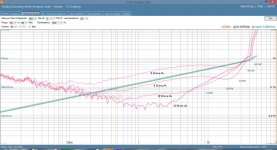
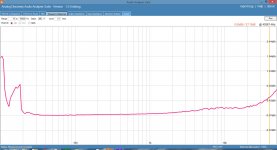
I’m also attaching a couple of graphs showing the frequency response at about 1W and 20W. As you can see these toroidal transformers do ok. The 1W graph is very flat from 10Hz to 40KHz (no -3db point) and even at 20W the -3dB point is around 28Hz.
I have played a bit with unbalancing the tubes to create a DC imbalance in the OPTs. I find that at about a 10mA imbalance I can push the THD to over 1% under 100Hz, with little effect on higher frequencies. If the tubes are balanced at closer than 2-3mA there is very little effect. I found balancing the DC currents quite easy. I’ll try to post some graphs on this.
I’m sure there’s much to be improved here – I haven’t paid too much attention to the choice of capacitors and grid leak resistors – though I did a quick analysis to check I wasn’t too far off in terms of rolling off high or low frequencies.
I hope this wasn’t too long for a first post. Thanks again for all of you who post here – I have learned a lot from all of you. I would welcome any feedback and comments.
Richard
This is my first post to the forum, though I have been lurking for a while reading many interesting posts. I don’t have a background in electronics (I was a CS major) though I have a solid understanding of physics. A few years ago I built a single ended EL84 guitar amp kit for my daughter. At the same time I was experimenting with 630m radio beacons and needed a 100W RF amplifier for my experiments. I ended up building a dual 807 power amplifier based on a design from ARRL.
Fast forward to a few months ago. I had thought it would be fun to reuse some of my old RF amp components in an audio amp one day. Back in November I saw a design by triodedick for an 807SE amplifier that had been built by Mark of Blueglow Electronics. Watching his YouTube videos gave me the impetus to build one for myself. It’s still in breadboard form and may or may not make it to a chassis one day, but it was a fun project.
For my second amplifier I wanted to have a go at designing something from scratch. I realize that there’s nothing new under the sun, so by “from scratch” I mean picking the tubes, basic architecture and operating points rather than building or modifying an existing schematic. Not surprisingly, what I ended up with looks very similar to other designs out there. For the preamp/drivers I had bought some 5687 tubes from Parts Connexion during one of previous orders. They were on sale for $4.50 each and there weren’t many designs out there using them. This was good since I wanted to experiment for myself. I prototyped a few pre-amps and even a 1W SE design. Around the same time I had seen 829B/3E29 tubes and thought it might be fun to build a push pull amp. Posts seemed to suggest it had been done, but I didn’t find much in the way of designs (a good thing again.) Once I had the work underway I did find a few posts on GU29 PPP amps that gave me confidence it could work.
For the design I started by driving the 3E29 from a signal generator in class A mode to get the power supply built – screen, grid voltages, etc. I decided to go with a cathodyne phase splitter since I liked the simplicity. I found I needed two pre amp stages in order to get adequate gain – the 5687 tube being only medium mu. I will probably experiment with a 12AX7 at some point since I expect only to need one stage in the preamp. The first version was a single tube, push pull amp using a pair of Hammond 125ESE single ended OPTs wired together to make a PP OPT. I like these OPTs since they have taps for 2.5K, 5K and 10K impedance. I started with the 5K taps on each and then when I added the second 3E29 I moved to the 2.5K taps.
When I found posts on GU29 PPP amps I ran into people using toroidal power transformers as PP OPTs. Specifically, a dual voltage (115/230V) 9V transformer can be used as a 5K PP OPT by wiring the two primaries in series, and feeding the B+ voltage in the middle. I found an Antek transformer (AS-1209) for about $20 that I thought would be fun to try. I read posts about core saturation and DC currents and you’ll see I did a couple of experiments to see how much DC balance affected performance.
I’m posting the schematic of the amp – I have built both channels and am listening to it through Klipsch RP-160M speakers. It sounds good to me with nice bass response. Not that I’m an audio expert. I have been using the Digilent 2 PC oscilloscope with the free Audio Analyzer suite from “The Stuff Made” to analyze the amp. I’m including some stats and graphs that I made using the setup. I have tried idle plate currents in the 3E29 ranging from 10 to 30 mA per section at 425V. Here are some THD+N measurements made at 1KHz:
Bias Iplate THD+N@1W PWR@1%THD+N MaxPWR
-19V__10mA____0.29%_____37W______44W
-18V__15mA____0.10%_____40W______48W
-16V__20mA____0.04%_____36W______47W
-14V__30mA____0.02%_____36W______51W
I’m attaching a graph that shows these 4 curves overlaid so I can see the effect of plate current on THD. I think the 15mA test may be a bit off – I might not have kept the B+ voltage at 425V during the run. None of this is super accurate but I think it’s close. I’m choosing to run it at 20mA as a good balance between efficiency and performance. Max power doesn’t really mean much since THD rises quickly after hitting 1%.
I’m also attaching a couple of graphs showing the frequency response at about 1W and 20W. As you can see these toroidal transformers do ok. The 1W graph is very flat from 10Hz to 40KHz (no -3db point) and even at 20W the -3dB point is around 28Hz.
I have played a bit with unbalancing the tubes to create a DC imbalance in the OPTs. I find that at about a 10mA imbalance I can push the THD to over 1% under 100Hz, with little effect on higher frequencies. If the tubes are balanced at closer than 2-3mA there is very little effect. I found balancing the DC currents quite easy. I’ll try to post some graphs on this.
I’m sure there’s much to be improved here – I haven’t paid too much attention to the choice of capacitors and grid leak resistors – though I did a quick analysis to check I wasn’t too far off in terms of rolling off high or low frequencies.
I hope this wasn’t too long for a first post. Thanks again for all of you who post here – I have learned a lot from all of you. I would welcome any feedback and comments.
Richard
Attachments
Last edited:
I've already found one mistake in the schematic. The anode resistor for the cathodyne phase splitter is 15K and not 20K.
Richard
Richard
The 1M resistor on the phase splitter is on the wrong side of the 1k grid stopper. Otherwise very nice.
I've been saying toroidal PTs and OPTs sound great. The graphics back me up 🙂
I've been saying toroidal PTs and OPTs sound great. The graphics back me up 🙂
Ah yes - good point - I'll fix it. I ran into problems with oscillations on the parallel 3E29s that were solved by moving all the grid stoppers from the breadboard to being soldered directly to the sockets.
You were the person that put me on to the toroidals btw. At $20 each and that performance...
You were the person that put me on to the toroidals btw. At $20 each and that performance...
The 1M resistor on the phase splitter is on the wrong side of the 1k grid stopper....
Much less than 0.1% difference. (The 1meg is bootstrapped about 3X, so 3,000,000/3,001,000 or 0.999,666 of loss...)
Much less than 0.1% difference. (The 1meg is bootstrapped about 3X, so 3,000,000/3,001,000 or 0.999,666 of loss...)
If the 1M is on the grid side of the stopper, there is no stopper, no?
This circuit is stable without any compensation components? How could that be?
Mine was stable for months, then one tube yellow plated. Forget red platting, it was brighter than an 0A3 neon glow tube! I was told this was caused by self-oscillation.
I've since scrapped it. Now all my amps use sweep tubes connected as triodes. (6P45P, 6P36P, 36LW6)
So, do you think the cathode emission increased, causing anode resistance to fall? I can imagine it is conceivable that a high anode resistance combined with the inevitably high shunt capacitance of a toroid might act as compensation.
Good question. It does seem to be. I guess I never got around to figuring out this part of the design. I did see some oscillations earlier in the testing but they went away. I need to dig in and understand this part of the design in more detail.This circuit is stable without any compensation components? How could that be?
Was that your GU29 PPP amp?Mine was stable for months, then one tube yellow plated. Forget red platting, it was brighter than an 0A3 neon glow tube! I was told this was caused by self-oscillation.
I've since scrapped it. Now all my amps use sweep tubes connected as triodes. (6P45P, 6P36P, 36LW6)
Yes. It never ran away as triode connected, but it never made much power that way, either...
I was running 440V/220V screen though. Your 180V seems more sane. Meanwhile triode connection was only 320V
I was running 440V/220V screen though. Your 180V seems more sane. Meanwhile triode connection was only 320V
Sorry to hear it. Yes - I have found no real performance difference with the lower screen voltage. When I first started to experiment with operating points for the 3E29 I was using cathode biasing and a few times managed to get the tube to red plate by pulling excessive screen current. If you lost your anode connection for some reason I think you could melt down the tube that way too.
Richard
Richard
I am admittedly late to the party, however, I want to compliment the OP on the design. With a few component changes, (the anode resistor of the phase-splitting stage, as you caught), and the grid stopper position. And of course, as you found, that the grid-stoppers are best soldered directly to the valve socket pins. And star grounding if you didn't implement that.
I personally like indirect cathode heater potential raising… by about 30 volts or so. Its almost trivial to do with a voltage doubler on the 12 volt heater tap, a couple of diodes, a pair of 22 µF capacitors.
Anyway, as KodaBMX and I have discussed elsewhere, the 10 kΩ 5 watt resistor is fine as a LPF (low pass filter) with the 100 µF can… yet its also a prime spot for a MOSFET and a resistive voltage-divider-plus-capacitor-to-gate source-follower. The voltage output can be whatever you select (230 V, in this case), but remains so independent of the draw of the tubes on the front end. So, it keeps the circuit more well-behaved as you adjust bias points and so on in experimentation.
Same goes for the unspecified B+ power supply. A simple MOSFET source follower with resistive gate-driving voltage divider (and a holding capacitor) is WAY better than most choke filtered supplies. And cheap. And relatively load-independent.
As I said.
Late to the party.
But not mute!
GoatGuy
PS: lastly, I kind of wonder “out loud” whether the anode-combo and cathode-combo resistors on the phase splitter ought not to be exactly the same in total value. Symmetry and all that. I know a lot of amplifiers don't have precise symmetry, for good reasons. I also believe that having asymmetry sets you up for intermodulation distortion. Just saying.
Thanks GoatGuy. I don't have this is a chassis yet so the ground is more of a buss that a star. I will move to star grounding in chassis. I could consider cathode heater potential though I believe I'm within spec for the 5687. I haven't tried any MOSFETs yet - it's an area I will have to learn about as I progress through this hobby. The B+ is based on a diode rectified 700VCT with a CLC filter 10u/10H/47u (based on what I had lying around). Screen is regulated by OC3 and OA3 tubes 🙂 I had wondered about balancing the cathodyne precisely. I will likely add another resister into the cathode to get the total to 15K - at least when I put it in a chassis.
Richard
Richard
How did you manage to balance the anode currents when you're at the mercy of the cathode current splitting between anode and screen?
I have 10 Ohm resistors in series with the B+ input to the OPTs (not shown on the schematic) and measure the voltage across them. Since I am using two separate primary windings on the OPTs I can measure the current going into each "half". That way I am actually measuring the current flow through the OPTs and balancing that. If I had a regular push pull OPTs I'd have to put the resistors on the anode leads to each tube pair.
I hope that makes sense.
I hope that makes sense.
Last edited:
For fun I just checked the screen currents. With 20mA per section anode current at idle I see about 0.5mA of screen current per section (for a total of around 4mA). If I drive the amp to its max (around 45W) I see that rise to about 5mA per section. From looking at the graphs for the tube I think that means I'm probably driving the grids slightly positive on the peaks at full volume. It's still well below the recommended screen current - which makes me believe I could drive the amp harder and get more power. One datasheet claims 44W per tube in AB1 - and I have two in parallel making about that.
So this low level means you could just control the cathode currents with current sinks if you wished.
I suppose so - if I were to learn about such things! I'm new to this and I have an ever expanding field of knowledge to acquire. Oh for a couple more lifetimes!
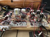
Here are photos of the amp and PSU. It's still all breadboard - not pretty but it works!
Here are photos of the amp and PSU. It's still all breadboard - not pretty but it works!
Attachments

- Status
- Not open for further replies.
- Home
- Amplifiers
- Tubes / Valves
- 3E29 (829B) Push Pull Amplifier