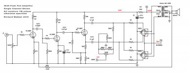
I love the somewhat Frankenstein look of the 829! A big knife switch for on/off would complete the picture.
If the 1M is on the grid side of the stopper, there is no stopper, no?
It still stops.
The grid stopper must be *close* to the grid pin. The wire in between is an inductance. The pin is a capacitance. This is a resonant circuit. By keeping the between-length very shore the inductance is small and a "small" resistor will spoil the resonant "Q", making oscillation unlikely.
A 1Meg to the side has no effect except the lead-length adding capacitance. This lead also should be short.
329B amps. Good job.
Oh darn, I keep looking at so many threads, but I do not have time to build all the amps I see.
So little time and energy.
Oh darn, I keep looking at so many threads, but I do not have time to build all the amps I see.
So little time and energy.
Last edited:
Thanks for the detailed notes - very much appreciated.
Here are some comments:
I only have a box of E12 1W resistors which is why I didn't specify the lower power values. It's also why I show 150K in parallel with 12K to make 11.1K. I agree that a standard 11K would be fine. I don't understand why it needs to be 2W. I think the current flow is around 3-4mA.
Capacitor voltage ratings are higher than needed because that's what I had -but I thought they could see the full B+ (sometimes over 450V) at start up before tubes warm up and start conducting.
On R7 being so high (2K2) - I don't quite remember why I chose that. I could lower the value and push the operating point up the load line - this may reduce distortion in this stage. I seem to remember dropping it down and it not making any difference. I'll check again. I don't know what you mean by adding an R22 1M resistor.
Capacitor values were also based on what I had available. I could drop C3 to 0.1uF. What I really want to do is a proper analysis of the RC combinations.
Thanks again!
Richard
Last edited:
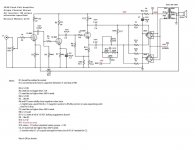
№ 1 — I only have a box of E12 1W resistors …
№ 2 — I don't understand why R12 needs to be 2W. I ≈ 3–4mA.
№ 3 — Cap V ratings … could see 450V+ before tubes warm up.
№ 4 — On R7 being so high (2K2) - I don't quite remember why I chose that.
№ 5 — I don't know what you mean by adding an R22 1M resistor.
№ 6 — I could drop C3 to 0.1µF.
(1) If I could "give points away", it'd be to you for using the term "E12", which absolutely demonstrates that you are familiar with (im-)precision standard values. Bravo, Richard! +10 to you! 10-12–15–18–22–27–33–39–47–56–68–82
(2) See R6, R7 comment re: 1,000 kΩ resistor (more below)
(3) Perfect reason.
(4) Without a grid pick-me-up (1,000 kΩ thing again), the higher 2.2 kΩ value works to increase headroom some. Not bunches. Its OK though.
(6) I appreciate your desire to do a more complete RC analysis. Note that one needs to deal with the “plate resistance” as well as load resistance(s) at each stage for the RC analysis to be reasonably accurate. So long as you are not driving any tube's grid into positive conduction, and so long as the grid-to-ground tie-down resistors are fairly high value (220+ kΩ, or actually just 10× the previous stage's anode resistance…), the first approximation works well:
Z = 1/(2πFC) … rearranging
C = 1/(2πFZ) … so for F = ⅓(20 Hz), Z = RGRID ≈ 220 kΩ
C = 0.11 µF
C = 1/(2πFZ) … so for F = ⅓(20 Hz), Z = RGRID ≈ 220 kΩ
C = 0.11 µF
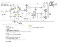
(5 out of order) I've gone on to annotate the drawing further, showing the 2200 kΩ resistor. See attached.
(7) I also added an audio-taper VR in the feedback loop. Awfully helpful in real-time, to tune in your preferred value. Changed the feedback resistor to 1.0 k, in order to allow for a limit-range.
A pleasure,
GoatGuy
Attachments
Last edited:
GoatGuy,
(1) Thank you!
(2) Still not sure why R12 needs to be 2W
(3) Great
(4) Headroom - that was it! I was estimating that the first stage would swing about 13V on a 1V peak input. The 2K2 gives about a -11V grid bias. I could probably do with a bit more - though I do think the amp clips in the 3E29s first - I will check again with a scope.
(5) Now I get it - you're using a voltage divider from the B+ to bias the tube. I've not seen that done before - nice - is it common? -17V is better that my -11V. And you used an E12 value 😉
(6) This is exactly the analysis I want to do. I did do a quick one a couple of weeks back I it didn't reveal much undesirable attenuation. This is next up for me.
(7) I did this earlier in the build and found that the 6K8 was the sweet spot. I used the 100K audio taper that is now my volume control! I could add one back in for further testing as a tweak the design.
Thanks again - this is fun.
Richard
Last edited:
GoatGuy,
(1) 😉
(2) R12 needs to be 2W: valve shorts, safety Same as 15 k anode R, for that.
(3) 🙂
(4) 🙂
(5) 🙂
(6) Good luck.
(7) See below
On point № 7, here is a "not-really-a-hack" that's pretty sweet. First, I'll assume you're making monoblocks.
Using a double wafer DP6T rotary switch, one wafer (pole) can switch in NFB injection resistances at varying fixed levels (good for dual monoblock configuration) quite easily. The "other wafer" (pole) is to do the same between the J1 input and the top of the volume-control VR.
Wait, what?
Yep, since increasing NFB decreases overall gain, you can compensate for that by inserting a suitable resistor in series with the volume VR to keep the overall "loudness" the same. (Unfortunately the volume-compensation resistor values must be empirically found. No formula works.)
I tell you, it really goes leagues in acoustically demonstrating the value (and compromises) of different levels of NFB. And being switched, tracking is perfect. Even between monoblocks … LOL.
It also allows you to have "leftmost-is–0-NFB" position, which is hard with the audio taper pots. My (ahem…) “customers” builds having this hack frequently report back that they like different NFB settings for different kinds of source material. Who'd've¹ known?
Just laughing with you,
GoatGuy
________________________________________
¹ Who'd've — I'm on a one-man jïhad to bring back the double contraction. Contractions are systematically expunged from all English-as-a-University-Subject classes, and double (and triple!) are the Antichrist hisself. Hence, I'm all in. Wouldn't've, y'all'd (e.g. Y'all'd better leave, cops a'near), and my favorite Americanism of them all… 'Tain't. as in the para-interjection “ 'Tain't so!”
Last edited:
piano₃;5726950 said:R12 certainly does not need to be 2W.
Yes, nominally so. But if for some reason the valve above it presents near ½ of the diminished 230 V B+ (i.e. around 115 volts), then
P = E²/R
P = 115² ÷ 12,000
P = 1.1 W
And while that's conveniently close to 1 W to just use a 1 W resistor for all intents and purposes, my own liking is having around a 50%+ margin above that. Closest is 2 W. Nuff said.P = 115² ÷ 12,000
P = 1.1 W
GoatGuy
I agree that there is no harm in over specifying resistors but I cannot see any possible idle condition with more than about 60V across the anode/cathode resistors. I am still concerned, however, that this amp will become unstable particularly as mains toroids have a low HF resonance.
I agree that there is no harm in over specifying resistors but I cannot see any possible idle condition with more than about 60 V across the anode/cathode resistors. I am still concerned, however, that this amp will become unstable particularly as mains toroids have a low HF resonance.
Wait… what?
First, haven't seen the power supply configuration. Early in the thread, I recommended use of a MOSFET source-follower style series regulator pair, one for raw B+ to 400 V supply, and another from that to the 230 supply. The almost absurd simplicity combined with excellent ripple rejection is enough to warrant it, if on no other grounds.
That they both add marked stability to the power, and thus to the amplifier proper is a nice bene. The mains toroids resonance hardly matters a whit.
I admit however, being an ignorant goat.
And I can personally attest to your excellent posts, elsewhere.
So… Baaa-aaa-aaa-aaa
Just ✔
GoatGuy
No, I don't mean the power supply; a mains toroid is being used as an output transformer and is included in the feedback loop. Maybe he has got lucky with a particular combination of HF phase shifts and there is no oscillation at present (maybe ringing though). I do think this will need further investigation once beyond the breadboard stage.
I may well be lucky on the oscillations. I did have some early on but correct placement of the grid stoppers put it to rest. I haven't checked with a square wave to look for ringing. Will do shortly. However, I really do want to do a proper analysis of the amp and add compensation. I have briefly looked at the topic and would welcome any pointers.
Richard
Richard
Optimisation of feedback is surely the most difficult thing in audio design. If you haven't done so, do all the gain and HF pole calculations and yes, square wave tests are the thing to do.
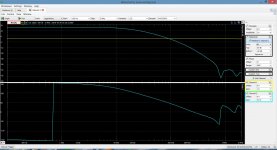
I'm still trying to learn about of all of this. I did manage to use the Network Analyzer feature of my Digilent Analog Discovery 2 to create a Bode plot of the feedback loop. I'm attaching the plot. I opened the loop at the +ve speaker terminal and inserted the signal at the 6.8K feedback resistor.
Here are some key values read from the plot:
Gain: 15.4 db (I calculated it as 16.6db GNFB so that's close)
Phase margin: 55.6 deg
Gain margin: 14.8dB
(From what I've read these seem decent)
Breakpoints:
135deg @ 14.7 KHz and 13.7dB
45deg @ 115KHz and -2.45dB
-45deg @ 609KHz and -32.7dB
I'm not sure if that second breakpoint is not negative enough gain? I don't have a plot to hand but I do see overshoot and a little ringing on a square wave. I'm still reading up on how to compensate. Any comments are welcome.
Thanks
Richard
Attachments
FWIW, i will choose the 5894 tubes, a single cathode makes for very good matching of sections, i have experienced red plating in one section using the 829b or the 832, you got to have lots of them to be able to chose a good match...
otoh, these tubes are very nice sounding....
otoh, these tubes are very nice sounding....
I only have the 4 3E29 tubes that I'm using in the amp. Perhaps I got lucky - I made no attempt to match them, though as you can see I am balancing the DC currents in the two halves of the push pull. At some point I'll try the amp with some 829B tubes and maybe the 5894 if I can find a quad at a reasonable price.
Richard
Richard
- Status
- Not open for further replies.
- Home
- Amplifiers
- Tubes / Valves
- 3E29 (829B) Push Pull Amplifier