I would just love to hear that we need not pay such close attention to these details of circuits and operating points. "I can't hear a difference" will allow us all to be less careful.
in the st70 the issue with unbalanced dc resistance was addressed using a capacitor from one side of the output traffo primary to the input feedback node...see eyelets 13 and 14...

crossover distortion is the issue at low volumes, that is why we bias tubes at around 70 to 80% of plate ratings to have the amps running class A for the first few milliliters...
TonyTecson,
Lots of good info from you. Thanks!
It seems to me that the negative feedback network of 390 mmf (390pF) and 1k Ohm feedback resistor do partially correct for any un-balanced AC of the output stage. That includes any AC un-balance of the output tubes, and the output transformers un-balanced DCR, and any turns ratio errors, if any.
We can change output tubes, match them, but we can not do much about the output transformer unless we change it (a little more trouble, and a little more expensive).
It does occur to me that when a simple modification can improve the DC current balance in the output transformer’s secondary halves, we are making it so that negative feedback has one less thing to correct. Once the output contains large very low frequency bass, no negative feedback will get rid of all the bass distortion, in fact it will add intermodulation distortion to the complex music tones.
The input Pentode had very little cathode to grid bias voltage. One additional thing that negative feedback did well was to “Lift” the cathode voltage to keep the stage from drawing grid current. Just one of those positive synergies.
CCS that are used to fix each individual cathode current can prevent unbalanced DC (but with all the other pluses and minuses).
The only negative feedback I know of that fixes core saturation due to unbalanced DC is special auto-bias that corrects for it (matches the DC).
I really liked the original Dyna Stereo 70, I thought it made good music.
Got it - balancing the cathode currents should get the desired outcome. Given mine is a parallel push pull design I could use both sections of a single envelope together, and then use the cathode current. However, I ended up having a push and pull stage in each envelope.no, just that cathode currents is in direct relation to plate currents,
you are correct to measure plate currents instead with the 832/829b tubes...
if using two bottles, that means 4 plate current monitoring resistors and 4 grid biasing adjustments....per channel...i dropped the idea of making this amp, i have my sights on the bigger tv tubes instead, like the 6hf5/6kd6's....
fyi. Cayin 500 used parallel 829b's..
fyi. Cayin 500 used parallel 829b's..
An externally hosted image should be here but it was not working when we last tested it.
You could do that. However I am treating the paralleled sections as a single tube - not trying to balance the current between them. As you can see I am using a single pot to balance the bias between the two halves of the push pull. So that means two current sensing resistors and one bias balance pot per channel. I also have one overall bias voltage adjustment since I don't feel the need to balance the channels that precisely.
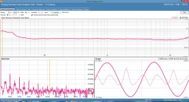
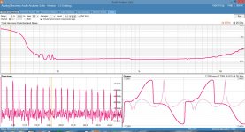
I ran some THD vs Freq tests varying the imbalance between 0mA and 20mA at 1W plus a couple at 10W. I'm attaching the results with some comments. Unfortunately the graphs are auto scaled so it makes it a bit harder to compare them visually, so I am providing some numbers to help.Looking forward to seeing the results. I was very surprised to find a 25mA misbalance that I couldn't detect with my ears at least at low power anyway.
All tests were at a nominal plate current of 44mA per envelope (i.e. 22mA per section).
0mA - 0.5% @ 25Hz, 0.09% @ 100Hz
5mA - 2.1% @ 25Hz, 0.5% @ 100Hz
10mA - 4.7% @ 25Hz, 1.1% @ 100Hz
20mA - 8.5% @ 25Hz, 3% @ 100Hz, 1% @ 200Hz
I'm also including a couple at 10W output:
0mA - 35% @ 25Hz, 0.15% @ 100Hz
20mA - 37% @ 25Hz, 2.7% @ 100Hz, 1% @ 300Hz
It's interesting to note that at 10W there is considerable distortion below 40Hz that is independent of current imbalance. Core saturation on these toroids?
Attachments
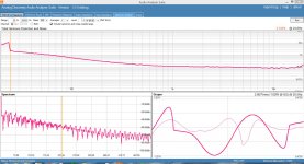

It's interesting to note that at 10W there is considerable distortion below 40Hz that is independent of current imbalance. Core saturation on these toroids?
From your schematic you are using a 9V power transformer as an output transformer. This means that it is designed for 9V on the secondary (about 10 watts into 8 ohms) at a frequency of 50 Hz. With a 10% design margin, the core would probably start saturating at frequencies less than 45 Hz. I have done similar tests with the same result.
Great post!
I have a bunch of 3e29s and 829bs I picked up at Nearfest in NH a few years ago. Im just getting into instrument amp designs and am breadboarding a 12AU7 preamp with MerlinB's excellent Tube Preamps 2nd edition as a ciruit tutorial. I also contest and chase cw and digital dx with over 150 countries confirmed.
I will take the time to look at your postings to see if I can make something useful out of all those NOS pentodes. Did you use 3e29s or 829b in the amp for which you posted the schematic? I was wondering about the much higher max plate of 5000 vdc on the 3e29s, and whether that implied more drive than the 2.5w the 12au7 offers.
BTW, did you wind your own toroidal opts? Does anybody or are they cheap enuf not to bother diy?
Have you seen El PasoTube Amps YT channel? He has some interesting vids on chracterizing opt impedances.
Chuck, ab1vl
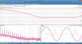
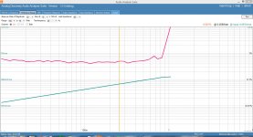
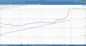
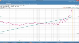
Interesting points. It's a 100VA transformer. I just ran some tests at 20Hz, 50Hz and 100Hz of THD vs power. I'm attaching the results (this is with balanced DC in the OPTs). Note that at 20Hz the THD goes through the roof at about 1W. At 50Hz it makes it to 15W or so before saturating and at 100Hz performance is starting to look like the 1KHz test with decent results up to about 30W.From your schematic you are using a 9V power transformer as an output transformer. This means that it is designed for 9V on the secondary (about 10 watts into 8 ohms) at a frequency of 50 Hz. With a 10% design margin, the core would probably start saturating at frequencies less than 45 Hz. I have done similar tests with the same result.
Attachments
Thanks! I built mine with 3E29 tubes (as per the schematic) and haven't tried it with 829Bs yet so can't comment. The toroidal power transformers I am using as OPTs are commercial - the Antek AS-1209 wired with the two 115V primaries in series and the two 9V secondaries in parallel (see my original post.)I have a bunch of 3e29s and 829bs I picked up at Nearfest in NH a few years ago. Im just getting into instrument amp designs and am breadboarding a 12AU7 preamp with MerlinB's excellent Tube Preamps 2nd edition as a ciruit tutorial. I also contest and chase cw and digital dx with over 150 countries confirmed.
I will take the time to look at your postings to see if I can make something useful out of all those NOS pentodes. Did you use 3e29s or 829b in the amp for which you posted the schematic? I was wondering about the much higher max plate of 5000 vdc on the 3e29s, and whether that implied more drive than the 2.5w the 12au7 offers.
BTW, did you wind your own toroidal opts? Does anybody or are they cheap enuf not to bother diy?
Have you seen El PasoTube Amps YT channel? He has some interesting vids on chracterizing opt impedances.
Chuck, ab1vl
Yes - I have watch a number of El Paso Tube's vids. He's a very cool guy!
Richard
WR6J
Interesting points. It's a 100VA transformer. I just ran some tests at 20Hz, 50Hz and 100Hz of THD vs power. I'm attaching the results (this is with balanced DC in the OPTs). Note that at 20Hz the THD goes through the roof at about 1W. At 50Hz it makes it to 15W or so before saturating and at 100Hz performance is starting to look like the 1KHz test with decent results up to about 30W.
That all makes sense. To a first approximation the ratio of voltage to frequency at saturation remains the same. So if you halve the frequency you can only have half the voltage before saturation, or quarter the power. Conversely at double the frequency you can double the voltage, or four times the power up to the point where amp clipping becomes the limiting factor.
The VA rating of the transformer doesn't really come into the picture. For a higher VA mains transformer the wire is thicker with a corresponding larger core allowing more current. The larger core allows for less turns per volt so of course the manufacturer takes advantage of this to save copper and the core still saturates at a frequency just under the design frequency (usually 50 Hz) and design voltage.
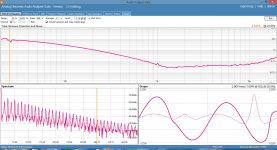
All tests were at a nominal plate current of 44mA per envelope (i.e. 22mA per section).
It's interesting to note that at 10W there is considerable distortion below 40Hz that is independent of current imbalance. Core saturation on these toroids?
What B+ voltage? How about increasing the current to 65mA/envelope?
I've always had better results using triode connection. The lower rp seems to improve LF performance. This is why I'm using 6P45S in triode with 320V B+ and 120mA / tube into 2 250VA coils in parallel. Also, I've never used anything by Antek, just Triad, but I get way more clean LF out of them than you seem to be getting. Too many variables to pin point it without more testing though.
Thanks for the analysis - what you say makes sense now. I can see that if the transformer is designed for 8V at 50Hz on the secondary (which translates to 8W into 8 Ohms as an OPT) then at higher powers and lower frequencies I can expect to run into core saturation.That all makes sense. To a first approximation the ratio of voltage to frequency at saturation remains the same. So if you halve the frequency you can only have half the voltage before saturation, or quarter the power. Conversely at double the frequency you can double the voltage, or four times the power up to the point where amp clipping becomes the limiting factor.
The VA rating of the transformer doesn't really come into the picture. For a higher VA mains transformer the wire is thicker with a corresponding larger core allowing more current. The larger core allows for less turns per volt so of course the manufacturer takes advantage of this to save copper and the core still saturates at a frequency just under the design frequency (usually 50 Hz) and design voltage.
B+ is around 400V. Increasing the plate currents doesn't seem to improve LF performance. On the other hand I cannot hear the distortion down at 20-40Hz. What kind of numbers are you getting? I might have to try a Triad.What B+ voltage? How about increasing the current to 65mA/envelope?
I've always had better results using triode connection. The lower rp seems to improve LF performance. This is why I'm using 6P45S in triode with 320V B+ and 120mA / tube into 2 250VA coils in parallel. Also, I've never used anything by Antek, just Triad, but I get way more clean LF out of them than you seem to be getting. Too many variables to pin point it without more testing though.
I don't have a distortion analyzer so I simply look at the voltage across the load while the sine wave looks clean. The last test I did was with a 12AV5GA triode connected amp running 60mA@320V. The clean power was 30W from 45Hz to 50kHz. 30Hz was about 15W. In theory, you should get full power from 50Hz at least, and anything lower is a bonus. The transformers were 100VA.
As far as an A/B comparison with a Yorkville AP1200, my monoblocs keep up with it to their power (about 120W or so).
As far as an A/B comparison with a Yorkville AP1200, my monoblocs keep up with it to their power (about 120W or so).
Today I did a few inductance measurements on a cheap(about 10 British pounds) 50VA toroidal transformer available from Rapid Electronics:
35V AC excitation 166H, 6V AC excitation 140H, 1V AC excitation 84H, all at 50 Hz mains frequency.
I have seen doubt expressed as to the suitability of mains toroids at low signal levels; these measurements seem to remove doubt for this particular transformer.
35V AC excitation 166H, 6V AC excitation 140H, 1V AC excitation 84H, all at 50 Hz mains frequency.
I have seen doubt expressed as to the suitability of mains toroids at low signal levels; these measurements seem to remove doubt for this particular transformer.
Just a reminder, the grid leak resistor of each half of the 829b should be less than 100k or less than 50k if you parallel the two valves together. The 829 wants to oscillate badly so neat construction and short wire lengths are of paramount importance.
Kobamx, i now use 190 volts for the screens and everything works better without oscillations, i did tried 220v but it was too much for my liking. BTW the sound is excellent, i am rediscovering my old music again.
I also have designed pcb's for an 6sl7 with mosfet cathodyne and 6p36s push pull, i believe that i will have it ready next month.
Chris
Last edited:
- Status
- Not open for further replies.
- Home
- Amplifiers
- Tubes / Valves
- 3E29 (829B) Push Pull Amplifier