I have not tried the inclination for two reasons.How about tilting the MDD slightly, think like Tower of Piza.
That way one could use longer guides (more guides) and avoid that the highs pass over your head (out of ”reach” of our ears).
One Could allso put the back/low part of the MDD in to a corner that will enhance the lows and lower mids.
What about that idea?
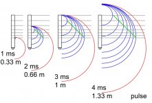
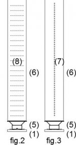
I expect the backward inclination to have the same effect as longer guides, sending the high frequency energy over the listener's head.
The tilt forward is equivalent to moving over the speakers, the point where the effect of delayed waves is lost as you can also see from the drawings published on the acoustic page. In any case, a reduced inclination forward would produce a reduced increase in length, with major problems in the construction of the base to guarantee a stable balance.
I hope to try waveguides flexible (spiral sheath for electrical systems), I need time because the possible directions and folding methods are numerous.
For now the best sound image is perceived on the side or just above the guides.
As with other loudspeakers, positioning in a corner strengthens the bass and the interaction with the walls can be both constructive and destructive at certain frequencies.
Attachments
Very interesting concept.
As this is cheap and easy to build I would like to try it by myself.
what properties should the driver have?
fs, qts ... ?
are Markaudio drivers suitable?
I am thinking of
- Alpair 7
- Alpair 6
- CHR 70
thanks in advance for your opinions
best regards
As this is cheap and easy to build I would like to try it by myself.
what properties should the driver have?
fs, qts ... ?
are Markaudio drivers suitable?
I am thinking of
- Alpair 7
- Alpair 6
- CHR 70
thanks in advance for your opinions
best regards
I would say from my limited experience, any of these would work if you modify the mounting and maybe scale up the pipe diameter for the larger driver - like use 25x25 mm instead of 20x20. Do you already have them? From what I saw in the datasheets, the Faital Pro 3FE25 or 3FE22 I used have something like 6 dB better sensitivity and larger power handling, but on the other hand, the Allpairs have higher Xmax.
I think the TS parameters are not too critical here, since the back is not in a box - as long as the Qts is ca 0.4 to 0.7, I would not expect any problems. I think the bass gets some reinforcement from the low speaker placement, but for higher volume listening, a subwoofer is definitely a good thing.
I think the TS parameters are not too critical here, since the back is not in a box - as long as the Qts is ca 0.4 to 0.7, I would not expect any problems. I think the bass gets some reinforcement from the low speaker placement, but for higher volume listening, a subwoofer is definitely a good thing.
Very interesting concept.
As this is cheap and easy to build I would like to try it by myself.
what properties should the driver have?
fs, qts ... ?
are Markaudio drivers suitable?
I am thinking of
- Alpair 7
- Alpair 6
- CHR 70...
Hi Spassgeneral
all the MDD projects I have published use a cabinet that is neutral to the speaker. The waveguides used to generate the delayed coherent wave fronts have the resonances distributed over an entire octave so that the acoustic energy can be transferred from the cone to the environment at all frequencies. For this reason I do not use TS parameters in the calculations of MDD projects.
I envy you to read a summary of my guidelines for MDD technology that I inserted in the first post of the thread: MDD Multi Delays Diffraction (Multi TL, omnidirectional, single drive, ...).
The speakers shown have excellent characteristics but I have not tried them. I am convinced that they will not generate problems related to TS parameters. They are all slightly larger, I think they also work with the same sections used in my projects but I cannot guarantee it. The 3fe25 has a declared efficiency of 91 dB, with these speakers you are a little below.
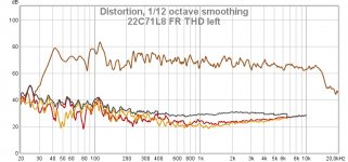
The best audio quality is that of the 22C71L8 project followed by the 22D7 project. Both require 1 or 2 days of work and around 100 euros of material, including the Faital-Pro 3FE25 drivers.
The work can be simplified and with around 50 euros, including the Faital-Pro 3FE25 drivers, 21M7 project or 54M42 projects can be realized.
If the appearance is important, aluminum or plexiglass can be used for waveguides. In this case the costs can multiply.
Compact designs 34C9 and 22C7 are lacking on bass. They can be a starting point for testing the MDD technology. For bass, you can choose the solution from several options.
The Pelanj build uses an amplified external subwoofer for the low range.
The Kec build uses a TL for the bass section.
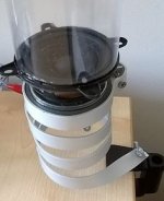
In the photo the 22C71L8 project, I understand any doubts but it sounds really good.
Attachments

As the Alpair 7 has a bigger Diameter than the faital the diameter of the guides has to be bigger as long that I stay with 7 guides..
I understood the cross section of the guides is important for the dispersion.
bigger diameter less dispersion on high frequencies.
does it make sense to use smaller diameters for the shorter guides and bigger diameters for the longer guides? so I can still use 7 guides at the greater Alpair's diameter. or is it feasable to make an adapter to reduce the cross section to fit the faital specified guides?
As for the membranes of the loudspeakers, if the section is increased, the directivity also increases. In this case, if the diameter increases, the fraction of acoustic energy sent upwards and not horizontally increases. For now I have only tried 25 mm PVC pipes for electrical systems and have never measured the relationship between diameter and high frequency dispersion diagram.As the Alpair 7 has a bigger Diameter than the faital the diameter of the guides has to be bigger as long that I stay with 7 guides..
I understood the cross section of the guides is important for the dispersion.
bigger diameter less dispersion on high frequencies.
does it make sense to use smaller diameters for the shorter guides and bigger diameters for the longer guides? so I can still use 7 guides at the greater Alpair's diameter. or is it feasable to make an adapter to reduce the cross section to fit the faital specified guides?
Using different diameters makes the calculation of lengths more complex as the sound energy emitted by each guide would change with the perimeter of the tube in a non-proportional way. Easier to use a square section with alveolar polypropylene as in the 54M42 project, the individual rods have a section of less than 1 cm2.
I would make an attempt with the same measurements as 22C7 project or 21M7 project using an adapter. Rigid PVC guides have a minimum cost (1 euro for 2 meters). In any case, a support bracket must be built to support waveguides and speaker. The same bracket can work to adapt the measures.
When I look at this, I'm thinking, why not take a large right angle triangle wedge of material, one of the legs being longer than the other, and fold it into a spiral, with one leg forming the center and the hypothenuse describing a descending spiral?
That way you'd avoid any resonant peaks.
I'm thinking that the turns of the spiral would have to become significantly tighter, towards the outside, so as to not have most of the sound energy escape through that low impedance escape.
That way you'd avoid any resonant peaks.
I'm thinking that the turns of the spiral would have to become significantly tighter, towards the outside, so as to not have most of the sound energy escape through that low impedance escape.
Last edited:
The resonance is pretty well spread even with just the 9 tubes. A 3D printed spiral version concept was shown in this post: 34c9 a MDD full range speakers.
I think I will try to build a 3D model of the 34c9 since my printer could print it in 3 parts - I wonder how much filament would that consume - I would guess not much more than the price equivalent on the Al tubes.
I think I will try to build a 3D model of the 34c9 since my printer could print it in 3 parts - I wonder how much filament would that consume - I would guess not much more than the price equivalent on the Al tubes.
Wow, that is a wild (as in looks like a wild animal (octopus)) speaker! Very cool!
Is that foam stuffed into the exits of each of the ports, and I am still not sure how higher frequencies make it out of the tube without a bunch of smeared time delays? What does the measured step response look like?
The smeared time delays are actually the main feature of this loudspeaker I think🙂
Here is the REW in-room measurement of my pair - left, right and both at the highest tube height in the middle of the stereo triangle with ca 1.5 m side lenght: 34c9.mdat - Google Drive
Here is the REW in-room measurement of my pair - left, right and both at the highest tube height in the middle of the stereo triangle with ca 1.5 m side lenght: 34c9.mdat - Google Drive
1 meter long round 9 section MDD with 4 mm outer wall thickness and 1 mm inner wall thicknes without the speaker attachment and rounding at 0.3 mm layer with 0.4 mm nozzle would consume 260 m of filament and take 60 hours to print for one piece (and 90 hours with 0.2 mm layer). With some extra for the speaker attachment, it would still be well in one spool. I would print in smaller pieces and one by one. So full 3D printing is actually feasible and with some cool looking filament color, maybe even no surface treatment would be necessary.
Attachments
wait
Greetings and thank you all for your interest. I'm traveling, the answers will come in a few days
Greetings and thank you all for your interest. I'm traveling, the answers will come in a few days
Hello all,
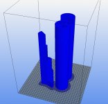
I have attached all the 3d printable files needed to print the spiral version seen here.
34c9 a MDD full range speakers.
It would consume about 1,3kg of filament to print one 100% solid. It is made for printers able to handle max height of 198mm.
I just got a 0,8mm nozzle for my printer so instead of continueing with the spiral version i will make another one that will be printable in Vasemode to recuse printing time and filament use.
Edit:Added STEP file for those who prefer that
Attachments
Last edited:
Thanks for sharing! So I will most probably print yours first, since it is a longer version and that is worth trying🙂
When I look at this, I'm thinking, why not take a large right angle triangle wedge of material, one of the legs being longer than the other, and fold it into a spiral, with one leg forming the center and the hypothenuse describing a descending spiral?
That way you'd avoid any resonant peaks.
I'm thinking that the turns of the spiral would have to become significantly tighter, towards the outside, so as to not have most of the sound energy escape through that low impedance escape.
Hi Squeak
I didn't understand the geometry you suggested well (a drawing would be needed). If you propose a single waveguide with small holes distributed on the walls I have already tried the solution in some prototypes with which I started the patent practice, then abandoned (acoustic diffractor and 665g prototype).
The single guide with multiple holes generates coherent and delayed sound wave fronts by diffraction (as in MDD projects) but does not simplify the problems of resonances. Many resonances distributed at different frequencies partially compensate each other. With a single guide you would always have only one resonance that should be perfectly matched with the driver and listening room.
Attachments

The resonance is pretty well spread even with just the 9 tubes. A 3D printed spiral version concept was shown in this post: 34c9 a MDD full range speakers.
I think I will try to build a 3D model of the 34c9 since my printer could print it in 3 parts - I wonder how much filament would that consume - I would guess not much more than the price equivalent on the Al tubes.
Hi pelanj
9 guides are more than enough to regulate the low frequency response. In some projects (22C71L8, 22D7, 22M7) , I only use 7 guides with a foam cube at the end of each waveguide.
To optimize the response to high frequencies, the length of the guides can be reduced to 50-60 cm by reinforcing the bass with a small sealed box. The recommended use is as a satellite in a system with separate sub or TL loading for rear emission. 3D printing times would be greatly reduced.
A practical use of the 3D printer could also be to create connection flanges between drivers and guides that are ready as square or round tubes to be cut to size. Soon I want to try a series of front guides with openings also at the base.
Wow, that is a wild (as in looks like a wild animal (octopus)) speaker! Very cool!
Is that foam stuffed into the exits of each of the ports, and I am still not sure how higher frequencies make it out of the tube without a bunch of smeared time delays? What does the measured step response look like?
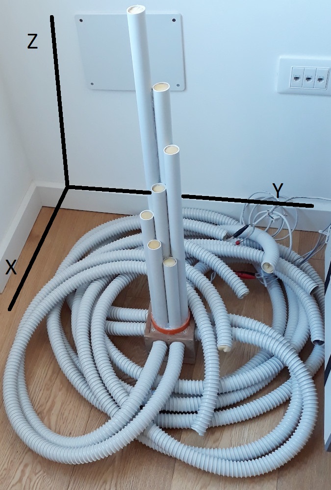
Octopus is one of the names I thought of, even spider is suitable, it has eight legs for the bass and 7 eyes (one is missing) for the highs. Then considering the average life of my prototypes, a few weeks, I stayed on alphanumeric acronyms.
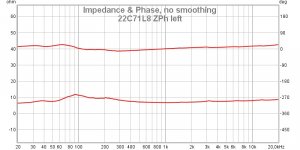
The foam at the exit of the waveguides is almost irrelevant to listening. The effect is evident only in the impedance graph. These are foam cubes of a few centimeters that can be easily removed.
The impulse response graph is not very significant as one of the objectives of the MDD technology is to create a series of coherent delayed fronts that complicate the interpretation. In the 22C71L8 project page you can download the REW file for further analysis.
- Home
- Loudspeakers
- Full Range
- 34c9 a MDD full range speakers.