\ Love pentodes more than triodes sound.
There is not much time to waste in life, because life's much too short for endless projects.
been there, done that, 12gt5 single ended pentode voltage amp is 6bn11 dual pentode, i made a facility for global feedback but since the amp was Shaded, there was no need....i love pentodes too....
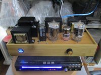
Attachments
Never wrote that I'm an electronics guru. Just the opposite is true, I have a humble respect for even tube radio or TV set designers, as I know that this is a hell of a lot more complicated compared for a simple power amp build project.
Did go one with other, more interesting tubes. Love pentodes more than triodes sound.
There is not much time to waste in life, because life's much too short for endless projects.
I wasnt attacking you, just a general statement to get the vinegar out of the conversation. Sometimes we forget there is a human behind the plaintext. And text is hard to interpet. A phone conversation is much more likely to go smoothly because you can instantly correct something if you say something tone-deaf.
Interesting, If you want il drop some pointers to pentodes in your inbox. there are a couple unknown telephone repeater tubes that no one seems to want or care for.. But are quite nice from a technical point of view.
Cheers,
V4LVE
Since the OP was suggesting C3m, can you guys look at this pentode model and give some constructive feedback as to what to improve? I've never used a pentode driver before.
If you want my 2C, use a wire wound resistor for the anode load. Nobody does because conventional wisdom says they are inductive. And they are, if you put them in a feedback circuit they will ring like a SOB, but for LF sometimes they do something with the sound. Inductance is too low to really cause an issue, but because audio is sometimes just a big Placebo you cant go wrong with a 50p resistor.
Vishay 4.7kΩ Wire Wound Resistor 7W +-5% AC07000004701JAC00 | RS Components
I really like the AC series of wirewounds, I have some vintage brown 10K 8W if you want me to drop some in the mail for you..
A resistor divider for C3g G2 will stabilize the gain somewhat as the tube ages. But this requires that you caclulate this with a Thevenin equivalent circuit to get it right.
The way you do this is quite complicated: It entails first eyeballing the G2 current from the datasheet for a couple of scenario's. and then mathematically optimizing the grid divider.
From the german language datasheet i gather that the amplification factor is about 40 from G2 to G1. If you know how much current G2 draws for a Bogey tube and take the end of life value for the G2 current. You can calculate the equivalent Thevenin resistance required of the voltage source that is the G2 divider. There are many ways of doing this.
Then you fiddle with a resistor combination that gives for example 75V at the G2 of the tube, and has a parallel resistance that is equivalent to the Thevenin resistance required you can stabilise the gain within a few percent. For any tube that is within the normal distribution given by the manufacturer even for tubes that test weak on a tube tester...
Example gracia, Say you work out that the tube IG2 current decreases with 0.5mA at this particular point on the curves as the tube ages. And you know the end of life value for transconductance or S at the end of life as well. you can use the Barkhousen formula to figure out the shift in gain at this particular point, Using delta Ri delta S.
Its a few hours of Excel nowadays, but back in the day some mathematical genius would have a daytime job doing this for the department. So now im curious if i can come to the same values as the datasheet.
A simple way of reasoning this is as follows: As the tube ages transconductance goes down and Ri goes up. the anode current and screen grid current would decrease, but because Ri dominates the anode resistor at this point, there is only a slight shift in anode voltage with age. By taking a divider for the screen grid, the decline in grid current will shift VG2 from 75V to say 80 or 85V and the inner gain of the tube will compensate the loss of gain due to an increase in internal resistance of the tube.
Last edited:
So true. Never have those misinterpretation problems in real life, this is just a forum thing I guess.I wasnt attacking you, just a general statement to get the vinegar out of the conversation. Sometimes we forget there is a human behind the plaintext. And text is hard to interpet. A phone conversation is much more likely to go smoothly because you can instantly correct something if you say something tone-deaf.
Interesting, If you want il drop some pointers to pentodes in your inbox. there are a couple unknown telephone repeater tubes that no one seems to want or care for.. But are quite nice from a technical point of view.
Cheers,
V4LVE
Thanks for your offer, but there are so many tubes on my radar, not enough lifetime for all those projects.
I'm OK for wire wound resistors - have plenty, thanks. Does the operating point make sense? Is 75v on the G2 right for around 150 on the anode? Is 12mA about right or what? It gives a 12.5K anode resistor which looks OK as long as there's a cathode bypass cap. I'd prefer to avoid that with a lower value cathode resistor and more current but I read that you should use a resistor on the anode and not a plate choke.
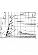
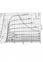
Heres two datasheet curve sets,
I think 200V G2 voltage has more evenly spaced curves right around 10mA or so. So is likely to be more linear. And have slightly lower distortion.
But if you want some higher 3H i suggest the 100V working point.
You can polder* it and meet somewhere in the middle. at around 150V G2 current, this is the best of both worlds IMHO so you dont have to cook the screen grid.
Polder* means wetlands in Dutch, we have some consensus driven decision making that mostly ends up being: lets make everyone happy and meet in the middle. I know politics is not allowed so thats the end of it as an adjective it is so common here.
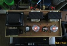
Attachments
Last edited:
Please drop your pointers in my inbox.I have some such "sleepers" in my collection and it's time to put them at work.If you want il drop some pointers to pentodes in your inbox. there are a couple unknown telephone repeater tubes that no one seems to want or care for.. But are quite nice from a technical point of view.
Heres two datasheet curve sets, I think 200V G2 voltage has more evenly spaced curves right around 10mA or so. So is likely to be more linear. And have slightly lower distortion. But if you want some higher 3H i suggest the 100V working point.
You can polder* it and meet somewhere in the middle. at around 150V G2 current, this is the best of both worlds IMHO so you dont have to cook the screen grid.
I read the following which persuaded me to think of a 75v glow tube
"fans of the pentode driver prefer that the difference between Ua and Ug2 on driver should be at least equal to the bias on output tube. This is because the anode voltage swing should not come below Ug2 value, because THD of driver tube then increases dramatically. "
I like "polder". I have introduced my son to the Norwegian "slapp av" which is a wonderful way of saying "relax".
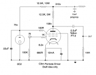
Since the OP was suggesting C3m, can you guys look at this pentode model and give some constructive feedback as to what to improve? I've never used a pentode driver before.
looks good to me...plate is at half b+ for maximum swing, g2 is regulated at 75 vdc....gm at 12ma cathode current and 150 vdc plate is around 3.5....therefore voltage gain is (12.5k*3.5 ma per volt) around x44...if you do not need this much gain, you can decrease the 12.5k to say 10k or even 8k....
Last edited:
fixed bias / with BITE (Built In Test).mooreamps: What are you referring to when you say "..and it would not be 880 ohm resistor bias"?
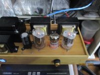
Attachments
Last edited:
Thanks guys for the material on the C3m - very helpful.
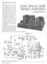
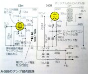
nicoch58 - as luck would have it your schematic also runs the C3m at 12mA, so I can't have been far wrong. I just used a glow tube, and had a bit less B+ voltage.
There are no voltages I can see on the Glass Audio schematic, unless I'm missing something. I have no idea why designers omit such essential data. Maybe it says something in the text. But thanks - useful info.
In the AAA forum, someone has build an ECC83-300B amp, just one system for one tube, so its equally a two stager. Even when its a triode and your using it pentode wired, the two tubes have similarities. His statement was, its the simplest of circuits to drive a 300B and it sounds very neutral. He couldn't spot nothing that could catch the ear. No extra dynamics, no sound, just a very neutral performer. Yours will perform the same way.
I'll call it the Accuphase sound, just with tubes.
I'll call it the Accuphase sound, just with tubes.
In the AAA forum, someone has build an ECC83-300B amp, just one system for one tube, so its equally a two stager. Even when its a triode and your using it pentode wired, the two tubes have similarities. His statement was, its the simplest of circuits to drive a 300B and it sounds very neutral. He couldn't spot nothing that could catch the ear. No extra dynamics, no sound, just a very neutral performer. Yours will perform the same way. I'll call it the Accuphase sound, just with tubes.
My 300b amp is already working with a much better driver and sounding excellent. I have 5 OPTs and output stages ready built, and several input stages ready built. I just modify them and switch them around. I always have at least one working amp. The driver tubes I'm looking for (and using) will be older and more rare European ones, not the later 9 pin ones. I'm going back to some of the older European tubes and enjoying what I'm hearing.
Thorsten was (is) one of the cleverest, funniest, most generous characters I ever met. He was always helping people for nothing - giving parts away, writing endless schematics on pieces of paper in pub meets, entertaining us all with his stories. Yes - he started out in a small house in North London stuffed full of audio gear when he worked for a hospital there, and there was hardly room to sit down. But through hard work and vision he made a good career in the audio industry. Good luck to him wherever he is. A wonderful, unforgettable person who made everyone's life richer.
I know he was (and thought maybe still is) the guy at AMR/iFi. My impression was that he wanted to continue to be active on the DIY scene but was reigned in. He also grew disenchanted with diyaudio.com. He moved on to a much less prominent forum.
And yes, I too think he was very smart, also very opinionated (he would have no problem going toe-to-toe with the provocateur), but very generous and engaging (he posted hand-drawn schematics to my questions on a design I was contemplating).
Finally, it seems that he worked hard after coming over from E. Germany while sharing his love of audio electronics and eventually was able/recruited to do his love as a career. I, for one, am happy for him.
Bill

Bill Brown,
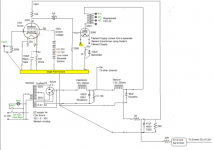
The 10uF across the parallel resistors in the SV83 screen voltage divider needs to be taken out (removed). Otherwise that capacitor passes the B+ ripple directly to the Screen, and on to the 22uF to ground. A 10uF/(10uF + 22uF) ripple divider.
The bottom resistor in the divider has the only cap that is needed (22uF) for the Screen resistive voltage divider.
The cross wiring of the rectifier plates is a good idea if the 2 rectifiers are not well balanced, one to the other.
The 0.68 Ohm resistors that drop the 6.3V to 5V for the rectifiers is a good idea.
It acts as a soft start for the rectifiers, because of the low cold resistance of the rectifier filaments.
Last edited:
- Home
- Amplifiers
- Tubes / Valves
- 300b with single stage driver, C3M or?