That's a very good example of how to direct couple output and driver stage with a single B supply.
If this were input/driver stage, place R1 plate side of L5 to decouple the winding capacitance, replace R2 with a suitable VR tube//bypass C (Ip <30mA) then you could remove C1 altogether.
If this were input/driver stage, place R1 plate side of L5 to decouple the winding capacitance, replace R2 with a suitable VR tube//bypass C (Ip <30mA) then you could remove C1 altogether.
Last edited:
In reference to Post # 488:
That is a nice circuit!
And nice loudspeakers too!
Suppose this is the best 300B amplifier, ever.
Then . . .
Here is what I notice (versus what Martin [low pitch] gives as the reason it sounds so good):
My theory:
C1, 47uF bypasses all the mid and high frequency currents of the 300B filament (“cathode”) to ground. It bypasses some of the bass frequencies too, but it has a low frequency limit when it no longer acts as a bypass cap.
Because of the 47uF bypass cap, there is no 300B filament (“cathode”) to C3gt cathode negative feedback. There is not a “common cathode string” at signal frequencies, only at DC and very low frequencies.
The (Local) Cathode feedback of the C3gt is R3, the 27 Ohm resistor to ground.
Given a Gm of 37,000 uMhos, the negative feedback would be 6dB.
But I doubt the C3gt Gm is that high.
I leave it to the ambitious readers to determine the operating Gm (and using the 27 Ohm R3,
to calculate the C3gt cathode negative feedback amount.
Just my opinions.
Last edited:
Is there any value to increase C1?In reference to Post # 488:
That is a nice circuit!
And nice loudspeakers too!
Suppose this is the best 300B amplifier, ever.
Then . . .
Here is what I notice (versus what Martin [low pitch] gives as the reason it sounds so good):
My theory:
C1, 47uF bypasses all the mid and high frequency currents of the 300B filament (“cathode”) to ground. It bypasses some of the bass frequencies too, but it has a low frequency limit when it no longer acts as a bypass cap.
Because of the 47uF bypass cap, there is no 300B filament (“cathode”) to C3gt cathode negative feedback. There is not a “common cathode string” at signal frequencies, only at DC and very low frequencies.
The (Local) Cathode feedback of the C3gt is R3, the 27 Ohm resistor to ground.
Given a Gm of 37,000 uMhos, the negative feedback would be 6dB.
But I doubt the C3gt Gm is that high.
I leave it to the ambitious readers to determine the operating Gm (and using the 27 Ohm R3,
to calculate the C3gt cathode negative feedback amount.
Just my opinions.
rchamber,
Increasing C1 capacitance will reduce the amplifier -3dB low frequency cutoff.
That might be good, that might be bad.
Possibly Good, very low bass frequencies will be stronger.
Possibly Bad, very low frequencies that are strong may saturate the output transformer laminations.
This may also be dependent on the whole playback system, including the loudspeakers, and how clean or distorted the loudspeakers are at low frequencies.
If this is the best 300B amplifier ever . . .
Will the secret sauce be ruined?
Only by using that exact system and listening to it, with 47uF, and then listening with another 47uF capacitor in parallel with the original 47uF will there be a definitive answer.
Just my opinions.
Thanks for your thoughts on the Amplifier Design in post # 488 , most it is over my newbie head but I've read through it a few times - 🙂
Well, I would offer that that is an admission of being mystified.Thanks for your thoughts on the Amplifier Design in post # 488 , most it is over my newbie head but I've read through it a few times - 🙂
I think that anyone reading here should begin, if you have not found it already, with reading, from Thorsten Loesch:
Calculating DC coupled Single Ended Valve Amplifiers - Part #1
and continue reading the follow on Parts.I did that many years ago and built that amplifier, which plays to this day in my system. It is a Loftin-White amplifier: 24A tetrode driving an EML 45 Mesh into a James JS-6123H configured for 5K primary impedance.
This amplifier was the second Loftin-White, aka chokeless monkey, amplifier that I built.
The first chokeless monkey amplifier that I built was from a post on the JoeList late one friday afternoon twenty or more years ago. I built it because I could not find the choke needed for a Full Monkey. It continues in rotation in my system to this day and is configured as: EL84 pentode driving 2A3C into a Magnequest FS 030.
I think it's time to build Martin's Full Monkey.
Very Best, Robert

A couple of simple solutions using one SIC diode in the cathode combined with a series resistor, no cathode bypass cap. Resistor load. Sounds good with either 6N1P or E180CC. The 6N1P is a little lighter in sound, possibly a trifle clearer. The E180CC is a trifle more full and solid. Hard to choose. They use the same circuit values except that the pinout is different for the heaters. I think the SIC diode used in this way works quite well, and allows the bypass cap to be avoided.

More experiments..... this time with a 6SN7 which has just enough gain in my system, or alternatives like 6J5. As regards the previous post, the E180CC is clearly better than the 6N1P. But if you can live with reduced gain the 6SN7 types are nicer. Not night and day better than the E180CC but better. And plenty of choice for tube rolling.
I've been switching between two circuits - one with a single SIC diode plus resistor in the cathode, no bypass, and the other with a single resistor and DC Link bypass cap. Attached circuit. Identical power supplies, source, speakers, audio tracks etc. The SIC version is a little sharper focussed but there's still a slight edge from the SIC diode. Just slight but you hear it on strings for instance. Could work on other types of music like rock and jazz. A safer all-round choice is the bypassed resistor. The sound is slightly more rounded but it's smoother and more pure. No edge - that's gone. So for classical music I'd go with that.


I've been switching between two circuits - one with a single SIC diode plus resistor in the cathode, no bypass, and the other with a single resistor and DC Link bypass cap. Attached circuit. Identical power supplies, source, speakers, audio tracks etc. The SIC version is a little sharper focussed but there's still a slight edge from the SIC diode. Just slight but you hear it on strings for instance. Could work on other types of music like rock and jazz. A safer all-round choice is the bypassed resistor. The sound is slightly more rounded but it's smoother and more pure. No edge - that's gone. So for classical music I'd go with that.
More experiments..... this time with a 6SN7 which has just enough gain in my system, or alternatives like 6J5. As regards the previous post, the E180CC is clearly better than the 6N1P. But if you can live with reduced gain the 6SN7 types are nicer. Not night and day better than the E180CC but better. And plenty of choice for tube rolling.
I've been switching between two circuits - one with a single SIC diode plus resistor in the cathode, no bypass, and the other with a single resistor and DC Link bypass cap. Attached circuit. Identical power supplies, source, speakers, audio tracks etc. The SIC version is a little sharper focussed but there's still a slight edge from the SIC diode. Just slight but you hear it on strings for instance. Could work on other types of music like rock and jazz. A safer all-round choice is the bypassed resistor. The sound is slightly more rounded but it's smoother and more pure. No edge - that's gone. So for classical music I'd go with that.
View attachment 1060810View attachment 1060811
What SIC diodes are you using? And curious what kind of voltage swing are you seeing at the grid of the 300B? I'm going to assume you are using some sort of preamp to be seeing enough gain out of a single 6SN7 for a 300B.
What SIC diodes are you using? And curious what kind of voltage swing are you seeing at the grid of the 300B? I'm going to assume you are using some sort of preamp to be seeing enough gain out of a single 6SN7 for a 300B.
Hi Stephe. SIC diodes in this case are Cree C3D02060F but you could use equivalents. I'm not using a 300b, in fact, I'm using 6B4Gs at book operating point 250v, 60mA, -45v. I don't use a preamp, just a DAC putting out the usual 2v line. As you may have guessed, I don't listen loud and with a 6SN7 the volume is just enough, none to spare - it's on max for normal listening levels but I listen just a little below that most of the time. Small room. I use exactly the same circuit with a E180CC driver tube for more volume. Sounds good, good tube.
I came up with this scheme and simulation some time ago. At my first free time I will make a working prototype. I have the material in stock! Only free time is a problem.

There are many DRD (Direct Reactance Driver) implementations based on Jack Elliano original theory (Randall amplifier).
A couple of Classic operating points . . .
6B4G / 6A3 / 2A3: -45V grid bias, 250V plate to filament, 60mA, RL 2.5k.
300B: -61V grid bias, 300V plate to filament, 60mA, RL 3.0k.
Required driver swing:
Asking a driver tube to linearly swing + /- 45V (90V p-p) is one thing,
Asking a driver tube to linearly swing + /- 61V (122V p-p) is more difficult.
Required driver gain:
For the required fixed signal level from a CD player, the second case requires 1.355 x more gain (+2.64dB) in order to get full amplifier output power (and then you will get the 300B output power that is more power than the 6B4G / 6A3 / 2A3.
Just my opinions.
K&K Audio ... Poof ... Gone ...

Effective immediately, please contact Holger Schaarsmidt at erhardaudio@gmail.com for any transformer order inquiries.
It has been my pleasure getting to know all the great customers over the years! I will miss you all.
Kevin
Please contact us for any questions.
Sorry to report.
Best,
Robert
Welcome!
You are here: Home
Notice:
After 20+ years as the US distributor of Lundahl transformers, I have decided to retire to focus my time on enjoying life with my family.Effective immediately, please contact Holger Schaarsmidt at erhardaudio@gmail.com for any transformer order inquiries.
It has been my pleasure getting to know all the great customers over the years! I will miss you all.
Kevin
Please contact us for any questions.
Sorry to report.
Best,
Robert
Hello,********************************************************************
- Hello, I may have something relevant ---
-- I saw the title of the thread and had to pass along some interesting information , I was just out cruising around a while back and ran into this thread on the Lenco Heaven Forum .
- They are sharing what they are using in their current systems and this gentleman said that - he has built MANY 300B Amplifiers in the past and had recently decided to build a fairly simple 300B Stereo Amplifier for his son for Christmas out of some extra parts he had out in the shed ...
- And he was So AMAZED at HOW GOOD it Sounded that he decided to build himself a pair of 300B Monoblocks using the Same Design and then said that it was Much better than any 300B he had built in the Past -- !!!!!!!!
( the fellows name is Martin , his Username is low pitch )
---------
Here is the Quote from the thread --
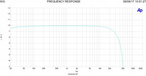
" Power amps below, SE 300B with choke loaded c3g driver run off the cathode - the Full Monkey . I built many 300B drivers but this circuit really stands out. I think it must be the local feedback you get from the common cathode string. I built an amp for my son for Christmas from shed junk and it was the best thing I had ever done. So I made a pair of mono blocks for myself. It's a really simple build, great for diy. TentLab filament supplies. There is a 6AX4 tube diode on the power transformer centre tap for slow warm up. (500-0-500V CLCLC)"
------------------------
- If you are interested here is the Link to the Thread --
- https://www.lencoheaven.net/forum/index.php?topic=25680.0
Here is the 300B Amplifier Schematic he posted --
View attachment 1039870
here is the Monoblock he built for himself -
View attachment 1039873
View attachment 1039874
And here is the double deck Stereo version of the Amplifier he built for his son for Christmas -
View attachment 1039875
----------
For fun here is his system -
View attachment 1039877
View attachment 1039878
- Hope this is helpful for someone , I am thinking of maybe building a pair in the future -
Thanks,
Kind regards, Dean
The 200H choke in Martin Seddon's Full Monkey amp shown in Post #488 has re-appeared on ebay:
Valab 200H Anode / Plate Chokes for Tweak Modify Your Tube Amp --- One Pair
eBay item number: 304540976397RC
Hello,
The 200H choke in Martin Seddon's Full Monkey amp shown in Post #488 has re-appeared on ebay:
Valab 200H Anode / Plate Chokes for Tweak Modify Your Tube Amp --- One Pair
eBay item number: 304540976397
RC
Searching ebay with that item number does not work. It is easier to just search for <Valab choke>...works. RC
I have a simple solution which offers a choice of gain for the input stage. Fit 2 sockets, an octal and a 9 pin one, and wire them together. You can then use either a 6SN7 input, mu 20, or an E180CC input, mu 46. Same circuit and component values. You can also fit 2 octal sockets and use 6J5s.


I have tested the circuit in attach.
And the frequency answer of input stage with a srpp of E88c
Input is 450 mV and out is 20 volt with a reasonable low Z
Then the frequency answer at 8 w 8 ohm
I think it is interesting solution
And the frequency answer of input stage with a srpp of E88c
Input is 450 mV and out is 20 volt with a reasonable low Z
Then the frequency answer at 8 w 8 ohm
I think it is interesting solution
Attachments
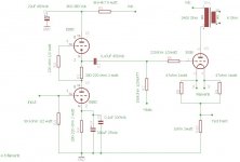
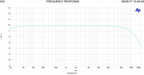
A classic schematic. The frontstage is a normal srpp so the gain is not that much, about 1/2 mu (about 16X). You need a line amplifier with enough gain and output voltage to drive it at full power. The bandwidth of the drive stage is good enough (>100kHz) but after that the transformer dictates the bandwidth, and I think you'll be particularly troubled by the steep end which is very steep. This means resonance problems
Look at the slope of the srpp and then of the whole amplifier. This is typical of a transformer that is not very well designed. An LL1664 would be a lot, I mean a lot better. (And a ll1664 is not a very high quality transformer)
For everything to work properly, there would have to be a filter that filters the high so there is no overshoot.
Not the best idea but otherwise we have to look for a better transformer.
Ohh, i noticed later on: an input of 450mV and an output of 20 V for the driver tube? Gain 44,44.? That is strange... probably at the 300B output .
Strange way to measure things......
You really have a strange way to measure circuits........
Last edited:
- Home
- Amplifiers
- Tubes / Valves
- 300b with single stage driver, C3M or?