Strange is what Thorsten write ,C3g is not so good for 300B ,maybe relate to swing ?in the present context, I would not dare to claim that the C3m is more adequate than the C3g.
I don't remember well need to research is post ....
when running triodes that have low rp, you can get away with global feedback....
i mean no global feedback needed....this is a 12gt5/6bn11 all pentode without global feedback...
Attachments
There's that moment when you think "Oh , maan." when the person being interviewed gives an answer that leads straight to the goods , and the interviewer, instead of asking the only question there is to ask, changes the subject. Why, George ! Why!!!
I don't use GNFB, or any type of feedback that includes the output transformer.
This was taken from my nine line synopsis of this long thread that expresses more opinions that facts. Everybody has their own opinion, many based in fact, and many are valid for a select audience, but may not be valid for all possible applications. I just added mine.
My amps have always been about getting the best possible sound for a reasonable outlay of cash. One could certainly buy the most expensive components possible, and arrange them into an amplifier using a "minimalist" design, and make a good sounding amp if it was not driven near clipping (due to blocking / bias shift). That has been done before, and for some is the only valid path to audio nirvana. There are other valid paths too. I tend to use OPT's in the "affordable class" and design a circuit to make the best of them. Blindly applying GNFB can be hit or miss in these cases.
One could wrap GNFB around an entire amplifier to improve it's measured performance. This will improve some aspects of the sound quality, and may degrade others.
It is a measurable engineering fact that applying GNFB around a circuit containing poles and zeros will degrade the stability of the entire closed loop system. It is possible to design and build an excellent audio amp with one GNFB loop, or many loops working in unison (Citation II comes to mind), but one better have a very good understanding of the engineering and testing needed to do so, and use very good OPT's with a good understanding of their characteristics.
All OPT's will have a zero at DC and a pole somewhere (hopefully) above the audio frequency range. Many other less dominant poles and zeros exist due to unwanted strays like leakage inductance and various winding capacitances. These will cause phase and amplitude shift at the frequency extremes which are often within the audio frequency range.
Dropping a budget OPT into a Citation two will likely lead to a sonic mess, unless every feedback loop in the amp is re-optimized for the situation. To a lesser degree picking a typical schematic from the web, and building it with whatever Hammond or Edcor iron that happens to fit the budget may or may not result in excellent sonics over all possible operating use cases. Amps with low phase margin can sound good with some signal sources, but "not right" when hit with a recording that excites the frequency / amplitude areas where instability is near.
Using the methods found in Morgan Jones books like "socking the dominant pole" and "staggering the poles" can make them work, but how many DIYers actually understand the concepts, or why they are necessary, and can effectively apply them?
My SPP amplifier is a copy of a typical push pull tube amp. I asked my readers what they wanted after the SSE was designed in 2007, and a "simple PC board" version of an amp often seen in these pages at the time was the most popular answer, so I made it. It can incorporate GNFB, and for proper use one should tweak the compensating cap with a square wave and a scope, but virtually nobody does that.
I have found that the best way to get a low DF with good sound and without test equipment is to make the impedance driving the OPT as low as possible to reduce the dominance of strays, then avoid using GNFB from the secondary.
Feedback from the secondary to the cathode of the output tube can be (and is in the SSE) used to reduce the output impedance and improve the frequency response with some budget OPT's since it involves only the output stage.
Since the SSE and SPP designs from 15 years ago, I have been experimenting with various methods to reduce the effective Rp of the output tube to make the OPT look better. Most of the OPT's imperfections tend to fade from the overall loop equation if the OPT is driven by a perfect voltage source (zero output impedance).
The 300B with its Rp in the 800 ohm range is a good start. Its low Rp and wide operating conditions "sweet spot" is why it has been so popular over such a long time.
A long time ago Schade showed that local feedback wrapped around a pentode can create triode like Rp and performance. Capacitors in series with this feedback can create instabilities at LF. My CED / Unset design reduces the local feedback to a simple resistor directly from plate to control grid. Testing by myself and others here have shown it to be effective for the output stage, and for any intermediate stages.
It has been shown that successful application of local or two stage feedback in this manner can reduce the amplifier's output impedance to nearly only the effects of the DCR in the OPT, so why would I need or want GNFB?
One could still add GNFB to further improve the measured specs of an amp if done properly, but I don't find it necessary. Other amp designers might.
"Using the methods found in Morgan Jones books like "socking the dominant pole" and "staggering the poles" can make them work, but how many DIYers actually understand the concepts, or why they are necessary, and can effectively apply them?"
If you have access to LTSpice, then you can plot the phase and frequency response at the various points inside the amp circuit and more importantly, see how they move about as you change component values. That makes it is less of a black art than it used to be, but still subject to how good the modelling is. It is completely safe to do and cost free, as opposed to experimenting to find or tune those changes by using only a soldering iron.
kind regards
Marek
Most of my designs start out in LTSpice including the recent CED / Unset circuitry. The simulator is pretty good at telling you what will NOT work. Once you get something that works in the mind of the simulator, it has a chance of working. The reliability of the sim is only as good as the underlying models it uses. Some tube models are really good, some are poor, most are in between. Transformer models, well that's a different story, especially when you don't have equipment to measure them. That makes THD and harmonic spectrum plots a bit (OK a lot) optimistic.
Again, the usual "buy the best parts to build the best amp" guys rarely use simulation.
Again, the usual "buy the best parts to build the best amp" guys rarely use simulation.
Thanks for that post George!
In terms of ending up with something I liked the sound of for more than a few days I hadn't had much luck with GNFB, cathode degeneration, and the kinds of feedback common in filters (phono stages and line level crossovers) .
In December though, I built a pre and power amp, both using a fair degree of stage local plate to grid as well as output plate to input grid feedback and was pretty surprised at the sound, which was very clean/clear without any sense of it being hard, glassy, sterile, or etc.
The power amp was particularly surprising as it only has an output power just over three watts yet puts out deep clean bass and is also able to control a 15" woofer pretty well. I put this all down to the hybrid circuit that nets lots of gain and allows in turn lots of feedback.
It raises more interest in whether a particular type of feedback affects resulting sound in a particular way - repeatably/reliably.
the EML put out che 300B with 2,5v filament ,nice for AC ...
Yes, and it can replace a 2A3, and it can be a *Mesh* valve. I've gotten a pair to replace Shuguang 2A3Cs in a *chokeless Monkey* amp (aka Loftin-White) that I built according to Thorsten's London Live DIY Hi Fi Circle newsletter and JoeList posts of many years ago. The amp I built is EL84 (pentode)/2A3C/ MQ FS 030.
Plays most Bop Era jazz at *Extra Groove* level...Grazie EML! Filaments are still AC, mit humpot.
Best,
RC
I have to say, it was quite comical reading this thread.
"I have the best schematics, they are so great if anyone saw them, they would say they are the worlds best. This is so simple, but only I know how to do it. But I'm not going to show you, and it's a shame none of you can afford the parts I use."
I think that pretty much sums it up, oh and showing pictures of oversize transformers 😛 lol

I have to say, it was quite comical reading this thread.... oh and showing pictures of oversize transformers 😛 lol
If you want to start a contentious thread, start one on how to build a 2 stage 300b SE amp!!!
I think this has been a good thread, with lots of suggestions by some knowledgeable contributors, and I hope it continues. There may never be a perfect answer - if there were everyone would be using it. There are several "very good" answers, hence some "very good" 300b SE amps out there. But the beefy, great sounding DHT with a mu of 40 that everyone can afford doesn't exist, to my knowledge.
About the transformers - if you mean 50ae, his transformers have been very well received by guys like Ale Moglia and others who certainly know their stuff. I'd like a pair myself.
I've ask once but no answer, why isn't anyone using Shunt Cascode by Rod Coleman, Im very sure it will make a very good 2 stage amp.
If you want to start a contentious thread, start one on how to build a 2 stage 300b SE amp!!!
I think this has been a good thread, with lots of suggestions by some knowledgeable contributors, and I hope it continues.
So even though it uses two triodes, a cascode only inverts the signal once, so does that count as a 2 stage 300B amp? Enquiring minds want to know 😀
So even though it uses two triodes, a cascode only inverts the signal once, so does that count as a 2 stage 300B amp? Enquiring minds want to know 😀
Good question! i leave the answer to others......
But in any case, you've contributed a lot of value to 300b builds through your videos and experiments, and no doubt versions are being built as we speak. So for me it doesn't really matter.
... why isn't anyone using Shunt Cascode by Rod Coleman...
I sent an order to Rod in I think March of this year for the shunt cascode kit, and his reply was that he was out of boards and working on an improved circuit board, which might be available at the end of April IIRC. I let him know that I was interested and sent an inquiry a couple of months later, at which point he was still working on it.
I'm still interested but have heard nothing further from him...I'd be using it if I could get the kit.
RC
So even though it uses two triodes, a cascode only inverts the signal once, so does that count as a 2 stage 300B amp? Enquiring minds want to know 😀
a triode cascode is a pentode, so in my book is only counts as one stage...
the bottom triode is the transconductance stage with voltage gains, the top triode is a grounded grid stage whose function is to keep the plate of the bottom triode constant, the top triode has no voltage gain.....
so then the voltage gain is gm x Rl.....
Last edited:
Good question! i leave the answer to others......
But in any case, you've contributed a lot of value to 300b builds through your videos and experiments, and no doubt versions are being built as we speak. So for me it doesn't really matter.
Thanks 🙂
Unfortunately, the outcome of those "high end, ton of money" amps is, if it comes to commercial ones, often just a desaster. ...
...
...and plays wonderfull music. A german designer, Götz Willimzig, has proofed to better a 300B amp with just a simple PL82 tube. When it comes to real music value, the 300B had a hard time to beat the tiny PL82. It simply was more musical sounding as the legendary tube. Still cost just pennies. But you need the right speakers for it.
So, Schmitz77,
What do you have to back up that claim? How did he do dat? He must have used some stuff other than just a PL82...what stuff? They still cost just pennies. And, what are the "right speakers for it"?
Best, RC
Here's my SE 2A3 amp using the E180F. One nice point about the E180F, besides the fact that it is excellent sounding, is that it is cheap to buy. I bought a dozen and got several pairs that matched for plate current at the operating point. Note the choke is by Electra-Print and the voltage on the cathode of the E180F is just over 1V. I had previously used a 6N23P-EV in the same amp although with LED bias. Replacing the 6N23P was a major step forward in reducing "glare" and increasing transparency.
Hello Palustris,
Very nice to find this cousin of the Loftin-White/monkey on a stick amplifier in your post. Back in the day on the JoeList in the mid 90s this was called a *Full Monkey* amp and required a significant choke. Which I could not find at the time. Thorsten proposed a *chokeless Monkey* on the list and I built one using EL84 (pentode) driving 2A3s (later replaced by 2A3Cs) into Magnequest FS 030 OTs. I still listen to it as an alternative to the 24A/45/James JS-6123 Loftin-White that I also built. The 45 amp is in systeme now with EML Mesh 45s, and the 2A3 is on the bench awaiting some fine tuning and EML 300B 2.5s. These two amps have been running flawlessly for over a decade or two, playing the best of bop and Biber.
Back on topic...I'm working toward a 300B amp. Not sure what it will be. I've got the parts to do a genuine 91A with WE 310As and WE 300Bs. I've got the parts to do Martin Seddon's Full Monkey with a 200H choke and C3g driver. I'm waiting for Rod Coleman's Shunt Cascode Kit with, 635Ps and 636P-DUs on hand. And there are a couple of others...including yet another C3g driver version, a 46 or 47 driver...on and on.
Just trying to keep this thread going, and wondering about PL82s.
Best, RC
Using parallel instead of series feed
While not concerning the driver tube used for 300B outputs, I will make a plug to use a parallel feed circuit instead of series feed. While this requires more parts, there are several advantages.
Not running DC through the output transformer allows using a smaller, better quality core. My parallel feed transformer is permalloy.
The signal is routed through a different capacitor, which can be better quality. Since I am only using my SET amp for 500 hz and higher, I use a VCAP teflon capacitor for the parafeed cap, which is arguably better than the capacitors that most all SET amps run their signals through.
The third advantage of using parallel feed is that you can wire the output transformer as an autoformer, which reduces the distortion compared to using a transformer used conventionally.
Just something to think about....
Retsel
Last edited:
So, Schmitz77,
What do you have to back up that claim? How did he do dat? He must have used some stuff other than just a PL82...what stuff? They still cost just pennies. And, what are the "right speakers for it"?
Best, RC
Maybe I can help out.
The famous PL82 amp is a work of Mr. Götz Willimzig, formerly one of the editor of the german audio magazine "Das Ohr" (The Ear). This was a magazine published during the 1980's to 1990's and having been the first one without being dependend on advertisments and only publishes listening impressions of the tested gear, instead of building the test upon measurements in combination with an absolute scale of stars and ratings to give for the reader to rank the equipment. Götz later did write books (for example, this "Höchst Empfindlich" (Highest Efficiency)) book, where he introduced audio systems, that were able to work in combination with high efficiency speakers.
I think it was in this book, where he described this concept of a small SE amp, that heavily depends on an excellent PSU and therefore can bring all the qualities of that small pentode to life.
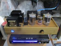
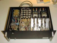
Here is a pic of a reproduction of that amp, and its visible that the PSU has become a substantial part of the search to extract the best sound of any electron tube. The circuit itself is relative simple, but engages a real good output transformer pair and good parts.
An externally hosted image should be here but it was not working when we last tested it.
Attachments
What do you have to back up that claim? How did he do dat? He must have used some stuff other than just a PL82...what stuff? They still cost just pennies. And, what are the "right speakers for it"?
Best, RC
If you're interested in this amp, start a new thread about it and I'll post what I found, including schematics.
As far as the speakers go, they would need to be very efficient as the amp runs the output tubes in triode and the claimed output is 0.5 wpc. The data sheet says it puts out 4.2w in pentode, albeit at 10% distortion.
- Home
- Amplifiers
- Tubes / Valves
- 300b with single stage driver, C3M or?