I am trying to understand why the 300B amps I have been working with have distortion much higher than what I see others reporting.
Most people I see posting FFTs show around 0.5% THD at 1 Watt out.
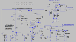
I have two each Psvane, Electro Harmonix Gold Lion, and LinLai WE 300B tubes. These vary from 1.4 to almost 3% THD at one watt into an 8 ohm load with the amp depicted in the attachment. The opt is a Edcor CXSE25-8-5K.
The driver is a Hybrid Mu-Follower set to 6.5mA. The schematic is missing the cathode bypass cap (1000uF). The driver is capable of 0.05%THD at 50Vrms with selective tubes (12GN7) The current driver is a 12HL7 which is giving between 0.13 and 0.14%THD. At this level, I do not expect much harmonic cancellation.
The drive voltage at the 300B grid is about 20.8Vrms for 1W out (varies slightly depending on the output tube).
Filament supply is a 5VAC transformer, bridge rectifier, 10mF cap, two 0.3R resistors and a second 10mF cap.
I have chosen an operating point from the WE datasheet of 5K, 350Vak, -76Vgk, 50mA Ia.
The measured operating point ended up at 349.8Vak, -78.6Vgk and 55mA Ia. This varies slightly from tube to tube.
The only configuration which achieved 0.5%THD was removing the bypass cap from the 300B Cathode resistor with one of the EH Gold Lion tubes. Unfortunately, this resulted in high IMD (0.1% vs 0.003% with the bypass cap) above 3KHz and thus is not acceptable.
Testing with the worst tube for THD (one of the Lin Lai) I tried several different resistors including Wire Wound and metal oxide film I have the following:
Ohmite Brown Devil WW 12W-------2.91%
Dale RS10 -------------------------------2.67%
Chinese Metal Oxide 5W parallel-----2.55%
Vishay WW 5W parallel----------------2.96%
TE Connect metal Oxide parallel------2.66%
Dale RS 5W parallel---------------------2.65%
I was using the ebay Chinese Metal Oxide resistors in my original builds, so I will continue using them as they show the lowest distortion.
I also tried a variety of bypass caps including Ryubycon Gold 82uF, United Chemcon Low ESR 330uF, and Epcos B32926 film capacitors (15uF). Anything 15uF and above seemed to have no impact on frequency response. None showed a difference in distortion.
Most people I see posting FFTs show around 0.5% THD at 1 Watt out.
I have two each Psvane, Electro Harmonix Gold Lion, and LinLai WE 300B tubes. These vary from 1.4 to almost 3% THD at one watt into an 8 ohm load with the amp depicted in the attachment. The opt is a Edcor CXSE25-8-5K.
The driver is a Hybrid Mu-Follower set to 6.5mA. The schematic is missing the cathode bypass cap (1000uF). The driver is capable of 0.05%THD at 50Vrms with selective tubes (12GN7) The current driver is a 12HL7 which is giving between 0.13 and 0.14%THD. At this level, I do not expect much harmonic cancellation.
The drive voltage at the 300B grid is about 20.8Vrms for 1W out (varies slightly depending on the output tube).
Filament supply is a 5VAC transformer, bridge rectifier, 10mF cap, two 0.3R resistors and a second 10mF cap.
I have chosen an operating point from the WE datasheet of 5K, 350Vak, -76Vgk, 50mA Ia.
The measured operating point ended up at 349.8Vak, -78.6Vgk and 55mA Ia. This varies slightly from tube to tube.
The only configuration which achieved 0.5%THD was removing the bypass cap from the 300B Cathode resistor with one of the EH Gold Lion tubes. Unfortunately, this resulted in high IMD (0.1% vs 0.003% with the bypass cap) above 3KHz and thus is not acceptable.
Testing with the worst tube for THD (one of the Lin Lai) I tried several different resistors including Wire Wound and metal oxide film I have the following:
Ohmite Brown Devil WW 12W-------2.91%
Dale RS10 -------------------------------2.67%
Chinese Metal Oxide 5W parallel-----2.55%
Vishay WW 5W parallel----------------2.96%
TE Connect metal Oxide parallel------2.66%
Dale RS 5W parallel---------------------2.65%
I was using the ebay Chinese Metal Oxide resistors in my original builds, so I will continue using them as they show the lowest distortion.
I also tried a variety of bypass caps including Ryubycon Gold 82uF, United Chemcon Low ESR 330uF, and Epcos B32926 film capacitors (15uF). Anything 15uF and above seemed to have no impact on frequency response. None showed a difference in distortion.
Attachments
Last edited:

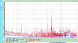
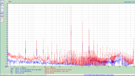
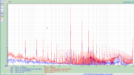
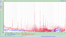
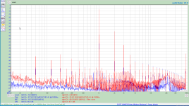
Here are the plots of the distortion. Note the sound card does not have a correction file in these and they are all shifted down about 5dB.
LinLai973 has the worst distortion, the Electro Harmonix Gold Lion have the best. Driver distortion is blue, output red.
LinLai973 has the worst distortion, the Electro Harmonix Gold Lion have the best. Driver distortion is blue, output red.
Attachments

I measured around 0.2% at 1 W with the JJ 300B biased at 85 mA, 400 Vak, 5 kΩ anode load. I'm guessing your results are due to the rather conservative bias point.
Tom
Tom
Thanks Tom.
I was looking at WE's table and find I have more distortion at rated output as well.
That said, I will try 400Vak 85ma tomorrow and report the results. 1050Rk?
I was looking at WE's table and find I have more distortion at rated output as well.
That said, I will try 400Vak 85ma tomorrow and report the results. 1050Rk?
As a quick and dirty sanity check the loadline calculator below returns 1.3% for those operating conditions.5K, 350Vak, -76Vgk, 50mA Ia
https://www.vtadiy.com/loadline-calculators/loadline-calculator/
I am so surprised the schematic is so complicated. The 300B bias point shall be 75~80mA. Also, the driver using CCS load would have less distortion cancellation with the 300B. These two factors would cause higher THD as your measured.
I believe the LTspice simulation would show the same result.
Johnny
Simple is the BEST.
I believe the LTspice simulation would show the same result.
Johnny
Simple is the BEST.
Try to raise bias current, as Tom suggested, and U(ak) too.
Sample:
My daily used (CCS loaded D3a, FET source follower, fix bias) 300B SE, 5k OPT.
Some -old- measurement with dissimilar 300B EH tubes at 70mA.
B+: 390V
EH300B (-81.0V, 70.0mA, 384V)
EH300B gg (-78.2V, 70.0mA, 385V)
PWR L_THD R_THD L_Ug THD R_Ug THD
1W 0.35% 0.31% 22V 0.11% 21V 0.12%
4W 0.86% 0.80% 47V 0.31% 45V 0.31%
6W 1.23% 1.08% 57V 0.39% 54V 0.38%
8W 1.52% 1.37% 65V 0.43% 63V 0.45%
9W 1.56% 1.43% 69V 0.43% 66V 0.45%
10W 1.57% 1.47% 73V 0.40% 70V 0.45%
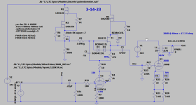
In part the schematic is complicated due to test circuitry (lower right) for protection of the sound card, and the necessity for an additional stage (5687) due to the low soundcard output of 1Vrms.
Previous experiments with harmonic cancellation led me to believe it is not reliable as it is very tube dependent, bias point dependent and frequency dependent. For this reason I am trying to minimize driver THD content.
The proposed final amplifier circuit is shown here:
Previous experiments with harmonic cancellation led me to believe it is not reliable as it is very tube dependent, bias point dependent and frequency dependent. For this reason I am trying to minimize driver THD content.
The proposed final amplifier circuit is shown here:
Attachments
After a morning of testing I have the following comparison of the best tube (Gold Lion) and worst tube (LinLai) distortion.
I tried several other driver tubes and found as expected that they have little effect on distortion.
Vak = 398.1
Vk = 88.1
Ia = 0.0796A
Power vs distortion %THD
Power----Gold Lion2---LinLai973
1W-------0.74----------1.76
2W-------1.15----------2.43
3W-------1.36----------2.91
4W-------1.59----------3.41
5W-------1.85----------3.80
6W-------2.16----------4.07
7W-------2.53----------4.46
8W-------2.69----------5.01
9W-------3.20----------6.09
10W-----4.47----------10.16*
* Driver clipping at 94Vrms
I used fixed bias. I didn't want to deal with 50 W rated power resistors. You can see the circuit here: https://neurochrome.com/pages/dg300bThat said, I will try 400Vak 85ma tomorrow and report the results. 1050Rk?
I used an ECC99 (common cathode) for the gain stage and a cathode follower for the driver. Driving a 300B is not easy. You want high voltage swing (85 V, peak, minimum), relatively high output current, and low distortion all at the same time.
I would try simulating the driver with a 100-200 pF capacitive load in place of the 300B. Look at the step response. It should be fast in both directions - or at least fast enough.
Tom
I would also investigate the distortion contribution of the output transformer. I run fixed bias of ~70mA at 400V and got around 0.45% thd at 1kHz and 1W with JJ300B and Monolith Magnetics 5K:8/16 output transformers. Measured when I was confirming the amplifier performance about 5 years ago. Driver is single D3A based hybrid mu-follower.
Thanks Tom, I will study your design. Fixed Bias was my next planned experiment.
When testing the driver, I used a cap across the grid resistor representing the 300B input during development. the 12HL7 and 12GN7 are capable of high drive voltage and current. To verify I wasn't slew rate limiting, I buffered the output of the 12HL7 with a FET source follower loaded with a current source and saw no improvement in THD or gain. I interpreted this to show that the 12HL7 had sufficient drive capability. I also calculated the Slew Rate limiting, but did so at 50Vrms which was sufficient for the previous 70V bias point. I need to recalculate for 90V bias to be sure.
TNT: No they do not. I am just trying to understand why I was seeing relatively high THD (bad operating point), and optimize a design of my own after having built a cascaded common cathode amp with 6SN7 driving 6Sn7 driving the 300B.
Kevin: yes, transformers do contribute to harmonic distortion despite what some have told me. High DCR in the primary especially can contribute as any power loss means the driving tube has to put out additional drive to overcome the copper losses. The higher the tube output, the greater the distortion. Magnetizing losses will contribute the same. Granted this is a small percentage of the total distortion, maybe 5% of the total?, but it is measurable and does exist.
The MM transformers look very nice but are out of my budget at this time. I have One electron UBT-2 UBT-3 and Edcor CXSE25-8-5K on hand so that is what I am using. The UBT-3 have excessively high DCR. so I have been testing with the Edcor transformers.
Assuming the generator, sound card, driver stage do not introduce significant distortion, I suspect you have not got really linear tubes.
I had the same issue with the 2A3s a few years back. Over 20 tubes, all made in US in the 50s, despite measuring spot on on Hickock transconductance tester at 4.8-5.2 ma/V and anode currents between 55 and 60+ mA they gave very different THD results. Most of them were doing 0.7-1% at 1W and only 3-4 of them were at 0.3-0.4%.
I had the same issue with the 2A3s a few years back. Over 20 tubes, all made in US in the 50s, despite measuring spot on on Hickock transconductance tester at 4.8-5.2 ma/V and anode currents between 55 and 60+ mA they gave very different THD results. Most of them were doing 0.7-1% at 1W and only 3-4 of them were at 0.3-0.4%.
That is my suspicion 45.
The ElectroHarmonix gold lion were purchased from Antique Electronic Supply IIRC. The rest through Ebay.
I suspect the LinLai may even be rejects that the factory sold "in country" and were then sold on ebay. Possibly grid misalignment? I find it interesting that the LinLai web site says to only buy through their web site. Where else would their tubes end up? Kind of makes one wonder why if they have proper quality control.
Last edited:
I've used the Edcor CXSE25-8-5K in my DG300B. I recall the THD being higher than with the Electra-Print transformers, but not dramatically so. I think it was 0.4 % vs 0.25 % with the E-P.I would also investigate the distortion contribution of the output transformer.
Output transformers do contribute to the THD. It would be a bit naive to assume otherwise. After all transformer saturation is a thing. Whether they're the dominant source of distortion is another matter. The CXSE25 should have no issues in this circuit.
You could measure the THD at the input to the 300B. That should give you a good indication of whether the driver or the output is to blame.
The JJ 300B tubes I used were pretty consistent in performance. I did have one where the bias shifted and the THD about doubled, but that was due to a mishap on my end. For some reason, during prototyping, I ended up running 200 mA anode current for long enough to make the plate of that one tube glow dark red. That tube forever ran at a few volts higher Vgk and a bit higher THD than the rest. I guess it got burnt in... 🙂
Tom
TheGimp,
I am sorry for the long following analysis, but it may help to explain the distortion levels you are getting.
Here is a compilation from the Western Electric Data Sheet for the 300B tables (not the curves, the data sheet that also has tables):
350V plate to filament; -76V grid to filament; 50mA plate current; 5k Ohm load impedance.
Western Electric Table Results:
6.2 Watts output (from the tube; not the output transformer secondary).
-30dBc 2nd Harmonic
-45dBc 3rd Harmonic (notice the classic 'well behaved' 15dB difference between the 2nd and 3rd harmonic distortion levels)
And -30dBc 2nd Harmonic distortion is 3.16% at 6 watts from the 300B plate to the output tube to the primary (need more than 6 Watts to get 6 watts from the output transformer secondary).
Now, let's do an approximation of backing down the signal drive to the grid, so that we get the plate to put out 1 Watt (not the transformer secondary output) . . . (calculating in round numbers)
1 Watt is 7.9 dB less than 6.2 Watts.
- 30dBc - 7.9 db = -37.9dBc 2nd Harmonic distortion at 1 Watt.
-37.9dBc is 1.27 % 2nd harmonic distortion.
But that is at 1 Watt from the plate to the primary.
Let's take a transformer that has a 5k primary with 250 Ohms of DCR; and an 8 Ohm secondary with 0.4 Ohms of DCR.
The transformer's mid frequency insertion loss is approximately 1 dB.
But 1 dB of power loss is Power in / 1.26 in = Power out, in round numbers.
If we want 6 Watts out of the transformer secondary, we need 6 Watts x 1.26 = 7.56 Watts from the 300B plate.
But that means that the 2nd harmonic at 1 Watt from the transformer secondary is:
-30dBc -7.9db +1 dB = -36.9 dBc
-36.9 dBc = 1.43% 2nd Harmonic distortion.
Your mileage may vary . . . according to your output transformer loss, and your 300B tubes that you use.
I would expect a real Western Electric 300B might give a better distortion result, versus some of the other 300B tubes out there.
I hope you find this discussion helpful.
Last edited:
By "output", do you mean the output from the 300B into the primaries of the output transformer, or the output from the transformer secondaries into the loudspeaker load?Driver distortion is blue, output red.
Also, what did you use as a load for your measurements? A real loudspeaker or an 8 Ohm dummy resistor or something else?
- Home
- Amplifiers
- Tubes / Valves
- 300B with high harmonic distortion