That's from the notch created by the 6.8u cap and 0.05mH coil to kill the peak in the midrange FR, you can see it better here (left) and also what it would look like if you removed the coil and connected the cap directly to ground (right):What is this going on with the mid crossover? That rise in XO at the highest end?

Yeah I usually have to tweak the whole thing again when I start actually finding what values of parts I can actually buyOne tweak you should do with whatever xo you move forward with... Make sure all of the R, C, L values are standard values you can buy. For example if there's is a 0.68 mH inductor in VituixCAD switch between 0.65 mH and 0.70 mH since these are the readily available values. Also, look up the actual inductors you can buy and enter the actual DCR rather than what VituixCAD has estimated. Sometimes it doesn't matter, but sometimes it makes enough of a difference that you may change a component value to compensate.
Lol, missed that.... that will surely do itIt doesn't work that way. You have to input value for the mid "Y", i.e. distance from tweeter to mid axis, lets say Ymid=-130mm. Your 2.6 mm is value for mid "Z". Both Y and Z influence vertical directivity (lobing).
Cancelation is only in the vertical directivity (which is normal):
View attachment 1336694
Here is the horizontal directivity of the same crossover:
View attachment 1336697
Flip the polarity of the woofer. 🙂
How accurate is xsim at calculating wattage dissipation and can VituixCad do the same?
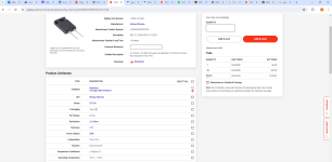
Also, can I use Mosfet style resistors with heat sinks? Will these non-inductive ones off of digikey work? They claim non-inductance. I would be using them with a heat sink attached.
https://www.digikey.com/en/products/detail/vishay-sfernice/LTO050F2R200FTE3/2712726
Also, can I use Mosfet style resistors with heat sinks? Will these non-inductive ones off of digikey work? They claim non-inductance. I would be using them with a heat sink attached.
https://www.digikey.com/en/products/detail/vishay-sfernice/LTO050F2R200FTE3/2712726
Attachments
For bigger value iof L use only laminated iron I core or ferrite/ferro-powder cylindrical core inductors. Those types of inductors have lowest Ohm resistance. Use air-core inductors only for smaller values of L and for tweeter filter.
@Sonce how did you think up that XO, it is absolutely inspiring.
@Bmsluite try US Coils, they have the best selection and good prices, you should be able to find the values you need. I'm cheap, I usually order what is need to make one XO and cover shipping then after I have a final ZO I will order the rest.
https://uscoils.us/
@Bmsluite try US Coils, they have the best selection and good prices, you should be able to find the values you need. I'm cheap, I usually order what is need to make one XO and cover shipping then after I have a final ZO I will order the rest.
https://uscoils.us/
Simulators are going to assume the maximum by default, ie the whole amplifier output at that frequency. This makes sense as a tool, but it's also not showing the most likely practical reality.at calculating wattage dissipation
Simplifying to get the same result with less components comes under normal optimising, but reducing parts count over a concern that parts inherently cause problems, isn't helpful.and try a less complicated design with about half that many parts.
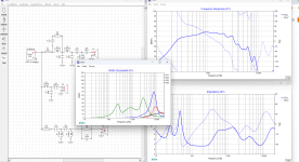
Here's another reduced-component crossover, with only one inductor in the woofer LPF section. In this design, the woofer is connected with positive polarity, while the polarity of the midrange and tweeter are both inverted. Note that any sharp cone breakup resonances are at least 35dB below the level of the summed response. A flat tweeter response has also been achieved.


For VituixCAD power dissipation...set the max output to the watts or voltage you determined in your box modelling such that the woofer hits xmax or xmax +10%. Then change the settings to "pink noise above 2000Hz with 13dB crest factor" for a reasonable approximation to normal audio power. (If anyone disagrees, feel free to correct me, this is advice I saved from someone else's post.)
Yes, I saw this and implemented them, however, I have heard of this thing called "saturation" which is supposedly a cracking sound caused by iron cores. One of the inductor is dissipating nearly 10 watts at full tilt. Would I be at risk of this salutation?For bigger value iof L use only laminated iron I core or ferrite/ferro-powder cylindrical core inductors. Those types of inductors have lowest Ohm resistance. Use air-core inductors only for smaller values of L and for tweeter filter.
I am going to run this against mine tomorrow.Here's another reduced-component crossover, with only one inductor in the woofer LPF section. In this design, the woofer is connected with positive polarity, while the polarity of the midrange and tweeter are both inverted. Note that any sharp cone breakup resonances are at least 35dB below the level of the summed response. A flat tweeter response has also been achieved.
View attachment 1336931
View attachment 1336936
Your inductance is very peaky. I have read that flattening the inductance makes the system sound more natural and in phase.
I guess then the argument is "are more XO components worse for sound than peaky impendence?"
Note that my impedance curve has been plotted over a reduced amplitude range for the vertical axis. That might have made it look a bit peakier than in the previous plots. The swings in the phase response of the impedance results are not very wide, so that side of things shouldn't be a problem.
Flattening the impedance curve above 100Hz would of course make it behave more like a pure resistance, without any reactive component. Solid state amplifiers aren't affected very much by a varying impedance, unless it strays into being a highly capacitative loading. Of course, if a tube amplifier with a low damping factor were to be used, then the variation in the loudspeaker's impedance curve would affect the amplifier's frequency response.
Flattening the impedance curve above 100Hz would of course make it behave more like a pure resistance, without any reactive component. Solid state amplifiers aren't affected very much by a varying impedance, unless it strays into being a highly capacitative loading. Of course, if a tube amplifier with a low damping factor were to be used, then the variation in the loudspeaker's impedance curve would affect the amplifier's frequency response.
Last edited:
Inductance doesn't dissipate power. You must be referring to the wire resistance, which has nothing to do with the core.One of the inductor is dissipating nearly 10 watts at full tilt. Would I be at risk of this salutation?
Allen,
What causes the saturation of iron cores? If I switch to an air core then resistance goes so high I have to redesign the crossover.
What causes the saturation of iron cores? If I switch to an air core then resistance goes so high I have to redesign the crossover.
Permeability, number of turns, Voltage applied. It's best measured.What causes the saturation of iron cores?
You don't have a problem until you have a problem, so try the iron core if you have it. Air cores can use heavier wire, they become larger, higher frequency performance should be measured.If I switch to an air core then resistance goes so high I have to redesign the crossover.
The actual ohm values of inductors off the shelf are really screwing my response up....... reality is annoying....lol
Look at Parts Express inductor selection. You have a choice of air core - small gauge wire (high DCR), air core - large gauge wire (medium DCR) and Iron laminate core (lowest DCR). If you are just trying to match one of the xo's designed so far, VituixCAD usually assumes a reasonable DCR, so one of these should get you pretty close. In your tweeter circuit (and maybe other places) small gauge air core probably are fine. In other places you have to decide. Large gauge air core are considered the best quality, but they have more DCR than iron laminate and can get pricey. Some people (I think there was a post earlier) don't like the higher DCR of air core because you loose some SPL but sometimes that actually helps your frequency response. Best advice...just play around with the values and get a good idea of the tradeoffs that you have.
I'm not being critical, I promise! 🙂
If I was doing this one I would trade off some of the flat frequency response for a smoother, downward sloping In-room response. (I think your blue line is probably power and you aren't showing IRR, but I assume it looks about the same.)
- Home
- Loudspeakers
- Multi-Way
- 3 way XO help