Thanks to John and shadowplay62!
And John, I understand the circuit but not frequency respond graph. How should impedance curve be interpreted? Is it the overall response from xover?
Another question: shall I keep C4 value of 220 uF? (150 + 72 = 222 uF in my case)
Doing this modification I might as well select audio components (though most of it is only marketing).
Looking at Mundorf MRES resistors (20W 2%). Not very expensive. They are 1,5 and 2,2 ohm, guess 2,2 is quite alright for the 2,0 ohm?
For 10 uF cap maybe ClarityCap again, but not sure since 4,7 uF ClarityCap didn't open up tweeter as expected. Thinking of solder back the old one. But maybe try your solution first.
Anyway, thanks for your efforts so far!

Thanks to John and shadowplay62!
And John, I understand the circuit but not frequency respond graph. How should impedance curve be interpreted? Is it the overall response from xover?
Another question: shall I keep C4 value of 220 uF? (150 + 72 = 222 uF in my case)
Doing this modification I might as well select audio components (though most of it is only marketing).
Looking at Mundorf MRES resistors (20W 2%). Not very expensive. They are 1,5 and 2,2 ohm, guess 2,2 is quite alright for the 2,0 ohm?
For 10 uF cap maybe ClarityCap again, but not sure since 4,7 uF ClarityCap didn't open up tweeter as expected. Thinking of solder back the old one. But maybe try your solution first.
Anyway, thanks for your efforts so far!
Your welcome.
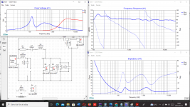
Yes its the simulated frequency respond graph and impedance curve.
Impedance lays around 5-ish and have lowest 3,2 ohm at 130 hz and highest at 1300 hz with 12 ohm
Also simulated how many volt your resistors will have at 100 Watt, 1,5 ohm resistor will have 16 volt and 2,2 ohm resistor about 13 volt at 3000 hz.
Al looks fine !
Attachments
Hello and thanks again!
I will try this modification but first go through this thread from start to (hopefully) get a better understanding of what I'm doing. Even downloaded xsim, just for fun, but one should have driver parameters, I guess, and I don't have them.
I'm aware of that the drivers probably are quite cheap but maybe of better quality than in later models. That's how it works, first version has fairly good components, after that production line savings begin.
So, for the time being I continue using old drivers, since I'm one of those raymondj described:
When these 707a hit the market reviewers wrote that they "disappeared", the listener could focus on the sound, not the speakers. Sound stage is impressing, extending far beoynd the speakers (on decent recordings, of course). A bit more "air" and I will be satisfied. Or probably aim for next improvement. Satisfaction doesn't seem to last long to us humans. But that's what diy is all about, right?
Thanks and take care!
I will try this modification but first go through this thread from start to (hopefully) get a better understanding of what I'm doing. Even downloaded xsim, just for fun, but one should have driver parameters, I guess, and I don't have them.
I'm aware of that the drivers probably are quite cheap but maybe of better quality than in later models. That's how it works, first version has fairly good components, after that production line savings begin.
So, for the time being I continue using old drivers, since I'm one of those raymondj described:
The sound with new caps, after 60 hours of listenening, is still a bit dark with a shy tweeter. So suggested modification is really interesting.I have never heard the originals, but assume they were decent enough for people to buy them in the first place. So even if they do look like cheap crap they may produce a good sound up to their power limits. Lots of people still like paper cones and stamped metal baskets.
When these 707a hit the market reviewers wrote that they "disappeared", the listener could focus on the sound, not the speakers. Sound stage is impressing, extending far beoynd the speakers (on decent recordings, of course). A bit more "air" and I will be satisfied. Or probably aim for next improvement. Satisfaction doesn't seem to last long to us humans. But that's what diy is all about, right?
Thanks and take care!
Attachments
It will be interesting to see how this plays out, Shadowplay62 Capacitor mod is definitely cheaper to implement and has one less component in the chain, for the same result. If you need more "air" you may end up end reducing the 2.2 ohm to the tweeter?
Personally after Xover mods it tends to be a good idea for me to verify the tweeter is wired correctly at the Xover and I haven't accidentally wrongly wired it up?
Maybe Jawen wouldn't mind inverting the tweeter polarity in XSim to see what happens to the Frequency response, as a reminder to us all.
Hello allIt will be interesting to see how this plays out, Shadowplay62 Capacitor mod is definitely cheaper to implement and has one less component in the chain, for the same result. If you need more "air" you may end up end reducing the 2.2 ohm to the tweeter?
Personally after Xover mods it tends to be a good idea for me to verify the tweeter is wired correctly at the Xover and I haven't accidentally wrongly wired it up?
Maybe Jawen wouldn't mind inverting the tweeter polarity in XSim to see what happens to the Frequency response, as a reminder to us all.
Yes, interesting to see what pelleplutt ends up with 👍
And i try to open the XSIM for my Jamo 707 simulation, but gets ERROR on file??'
Will try to solve this problem and come back.
Regards Jawen
Hello again,
Ordered components today to play around with. I will move slowly (as usual), making it step by step (one change at a time), to confirm audio effect (if any) of each modification. Would be nice to have xo hardwired outside the box, maybe a future project.
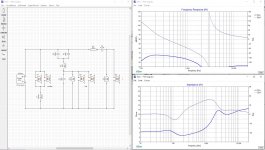
Ran original xo circuit in xsim but lack of driver parameters (exclamation mark on each driver) produced a weird frequency response, see image.
Jawen's xsim response is based on his new drivers and not on mine, right? But they shouldn't differ that much so I carry on. Always something to learn.
If you don't hear from me for a while it's because my speakers are on the operating table (or maybe I dropped dead).
Keep posting!
Ordered components today to play around with. I will move slowly (as usual), making it step by step (one change at a time), to confirm audio effect (if any) of each modification. Would be nice to have xo hardwired outside the box, maybe a future project.
Ran original xo circuit in xsim but lack of driver parameters (exclamation mark on each driver) produced a weird frequency response, see image.
Jawen's xsim response is based on his new drivers and not on mine, right? But they shouldn't differ that much so I carry on. Always something to learn.
If you don't hear from me for a while it's because my speakers are on the operating table (or maybe I dropped dead).
Keep posting!
Attachments
Yes pelleplutt, you can´t use XSIM without all drivers parameters/FRD file and ZMA file ( the impedance curve)Hello again,
Ordered components today to play around with. I will move slowly (as usual), making it step by step (one change at a time), to confirm audio effect (if any) of each modification. Would be nice to have xo hardwired outside the box, maybe a future project.
Ran original xo circuit in xsim but lack of driver parameters (exclamation mark on each driver) produced a weird frequency response, see image.
Jawen's xsim response is based on his new drivers and not on mine, right? But they shouldn't differ that much so I carry on. Always something to learn.
If you don't hear from me for a while it's because my speakers are on the operating table (or maybe I dropped dead).
Keep posting!
Or make parameters , a so called FRD file with a mesaured curve and then use SPL Trace in VituixCAD.
Think you orginal drivers/speaker will sound better with the changes, and of course even much better if you invest in the recomended drivers Faithal Pro and Sb tweeter
Received components today, hurray!
One quicky, what is this S1 component (LS) in parallell with R1 6,8 ohm? Protection? Should it stay on PCB when changing R1?
Hurray !
It´s called a thermistor.....And it work like a fuse for "over-voltage" protection.
Take it away because i think you can easy hear when the speakers getting to much=Distorsion !
Human ears are the best 👌
Thanks John for quick response.
Started out with one speaker, and of course I was too unpatient not to do more than I had planned.
This is how I did it:
Always hard to say if changes are improvements in the long run, but this is my initial observation:
But that was only one speaker. I am leaving home tomorrow and stay away this weekend. So hopefully time for the other speaker next week.
And then there is jawen's suggestion for the mid section.
And then maybe those Faithal Pro and Sb tweeter... 😎
Nice weekend to all of you!
Started out with one speaker, and of course I was too unpatient not to do more than I had planned.
This is how I did it:
- R1 6,8 ohm to 2,5 ohm (tweeter circuit). Chose Jantzen Audio Superes. Since they are 10 W and I was uncertain if that was on the edge so I chose two 4,7 ohm in parallell.
- Read two threads on thermistors on this site and decided to leave S1 on PCB.
- Moved ClarityCap 10 uF from mid circuit, now in series with R1.
- Soldered back the old 10 uF in mid section
Always hard to say if changes are improvements in the long run, but this is my initial observation:
- Got my "air", let's see if I get tired of it.
- Think I lost a bit of lower mid punch due to capacitor change to the original one.
- Overall, it sounds very good. Think I will dedicate the rest of my life to these experiments (not sure my wife agrees).
But that was only one speaker. I am leaving home tomorrow and stay away this weekend. So hopefully time for the other speaker next week.
And then there is jawen's suggestion for the mid section.
And then maybe those Faithal Pro and Sb tweeter... 😎
Nice weekend to all of you!
Thanks John for quick response.
Started out with one speaker, and of course I was too unpatient not to do more than I had planned.
This is how I did it:
- R1 6,8 ohm to 2,5 ohm (tweeter circuit). Chose Jantzen Audio Superes. Since they are 10 W and I was uncertain if that was on the edge so I chose two 4,7 ohm in parallell.
- Read two threads on thermistors on this site and decided to leave S1 on PCB.
- Moved ClarityCap 10 uF from mid circuit, now in series with R1.
- Soldered back the old 10 uF in mid section
You have missunderstand pelleplutt !
The resistor on R1 you have to take away., (and if tweeter is to high after, put a small resistor AFTER the cap NOT BEFORE)
The C4 cap 4,7uF you must change to 10uF
Both this is for your tweeter
And if you will try make some changes on your midrange, you have to:
Change the C2/C3 72 and 150 uF caps to a 120uF cap
/John
I wrote an answer yesterday, not sure where it went. Probably hit wrong button.
Anyway, I wasn't clear enough in post #391 so I'll try to clarify.
These changes made a huge difference to upper range. More clarity, clearer voices, more "air". Just what I wanted, thank you jawen!
Now to mid range. I've have new Jantzen eleCap 150 and 72 uF, but you (jawen) advices 120 uF once again. I'll start with one 150 uF but can order 120 uF if necessary.
One question:
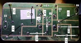
- Resistor before this 120 uF, not sure where to solder it on the "warm" side, towards +side so to say. See image.
This is a never ending adventure...
Anyway, I wasn't clear enough in post #391 so I'll try to clarify.
- Changed R1 from 6,8 ohm to 2,35 ohm (two 4,7 in parallell. 2,5 ohm was unavailable for quick delivery).
- Changed C4 from 4,7 uF to 10 uF.
These changes made a huge difference to upper range. More clarity, clearer voices, more "air". Just what I wanted, thank you jawen!
Now to mid range. I've have new Jantzen eleCap 150 and 72 uF, but you (jawen) advices 120 uF once again. I'll start with one 150 uF but can order 120 uF if necessary.
One question:
- Resistor before this 120 uF, not sure where to solder it on the "warm" side, towards +side so to say. See image.
This is a never ending adventure...
Attachments

Hello, hope you are all doing good.
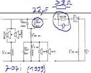
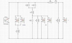
When studying my PCB compared to what I thought was my 707a circuit diagram I noticed something odd. Following power input, then each component to driver input and output, and then back to amp, it doesn't make sense compared to diagram. I thought my diagram looked like moorclos' 707i, with only two component values differing. But, if you shift (+) and (-) input from amp, diagram and PCB make more sense. Audio signals are ac, but phase should be important for the drivers.
So I shifted speaker terminal inputs and, voila, what a huge difference! Everything so clear, even bigger sound stage, deeper and tighter base. (I promised my wife to clean up the house, she arrives in 30 minutes and I haven't done a ****! Only been listening all day.)
Both Jamo and Rotel manuals advice connecting (+) to (+). Yet, amp(+) to speaker(-) gives best result. Anyone in for an explanation? Should my diagram be "mirrored"?
(Never mind component values on diagram, they are the original)
Attachments
Hello, hope you are all doing good.
When studying my PCB compared to what I thought was my 707a circuit diagram I noticed something odd. Following power input, then each component to driver input and output, and then back to amp, it doesn't make sense compared to diagram. I thought my diagram looked like moorclos' 707i, with only two component values differing. But, if you shift (+) and (-) input from amp, diagram and PCB make more sense. Audio signals are ac, but phase should be important for the drivers.
So I shifted speaker terminal inputs and, voila, what a huge difference! Everything so clear, even bigger sound stage, deeper and tighter base. (I promised my wife to clean up the house, she arrives in 30 minutes and I haven't done a ****! Only been listening all day.)
Both Jamo and Rotel manuals advice connecting (+) to (+). Yet, amp(+) to speaker(-) gives best result. Anyone in for an explanation? Should my diagram be "mirrored"?
(Never mind component values on diagram, they are the original)
Every succes is good Pelleplutt 👍
And music are better then cleaning hahaha.
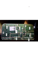
But photo is to small, i can´t se.
/john
Yeah, she forgave me, but not only that. Yesterday evening we sat down in the sofa listening to a bunch of songs she likes. And she was impressed! "I hear things I haven't heard before" she said.
Attaching larger image, hope Jawen can see better. Since my 707a seems to have an identical schematic as Moorclos 707i (and most of the 707's and also D590 except for a few component values), this is what puzzles me:
If you look at input signal from amp(+) and start with tweeter section, it connects to L4 and tweeter(+). That's not what schematic shows. But if you switch input polarity it suddenly makes sense (at least for tweeter section). Or am I just confused? 🤔
Anyway, for me this project is now about optimizing these speakers with their original drivers (just for fun, maybe shifting to new ones further on).
So I need driver parameters.
Moorclos provided some T/S parameters but none were for my drivers. I have spent several hours searching the web without success.
I would like to see if tweeter and mids response are balanced in the system.
Moorclos (if you're still with us): do you have more T/S parameters?
My drivers are: tweeter 38822, mid 20255, woofer 20383. PCB 53564
Then there is the possibility for mic measurements to create frd and zma files, but that seems like another mountain to climb.
It's Saturday, cheers! 🍺 (maybe too early in the day)
Last edited:
Yeah, she forgave me, but not only that. Yesterday evening we sat down in the sofa listening to a bunch of songs she likes. And she was impressed! "I hear things I haven't heard before" she said.
Attaching larger image, hope Jawen can see better. Since my 707a seems to have an identical schematic as Moorclos 707i (and most of the 707's and also D590 except for a few component values), this is what puzzles me:
If you look at input signal from amp(+) and start with tweeter section, it connects to L4 and tweeter(+). That's not what schematic shows. But if you switch input polarity it suddenly makes sense (at least for tweeter section). Or am I just confused? 🤔
Anyway, for me this project is now about optimizing these speakers with their original drivers (just for fun, maybe shifting to new ones further on).
So I need driver parameters.
Moorclos provided some T/S parameters but none were for my drivers. I have spent several hours searching the web without success.
I would like to see if tweeter and mids response are balanced in the system.
Moorclos (if you're still with us): do you have more T/S parameters?
My drivers are: tweeter 38822, mid 20255, woofer 20383. PCB 53564
Then there is the possibility for mic measurements to create frd and zma files, but that seems like another mountain to climb.
It's Saturday, cheers! 🍺 (maybe too early in the day)
Real quality when also wife "is on the train".........Me still single hahaha.
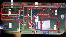
I have spend some hours to figure out how your xover goes.
And i can´t se "inside the PCB but have drawn the lines where things supouse to go.
The most importent when you look at my picture, is thatTweeter, Midrannge and Woofer possetive side goes somewhere between "the 2 component" that i draw, and the same with negative. ( And maby your tweeter is inverted on the scheme, you have to try it out...so possetive side can be negative )
And where i writes W+/-/+/- it means go to 1 woofer to + and from same woofer - to the 2 woofer +, and from 2 woofer - to negative on xover.
Good look
Regards John
Attachments
First of all I want to thank Jawen/John for starting this thread and for all the help he has provided. Also sending thanks to everyone else that has contributed, like Raymond, Moorclos, Belemakare, shadowplay62 and a few more.
I started following this thread without even the knowledge of how to reach the woofers which needed new surrondings (I couldl hear that). Now I am tweaking components in xover. That's a fairly steep knowledge ascendance! All thanks to you!
John, I feel ashamed you spent hours trying to figure out PCB coupling. I will study your image later. Maybe you are right about the tweeter originally being inverted. The Danish guys probably knew what they were doing.
I spent this afternoon listening to music and shifting speaker cables between (+) and (-) over and over again. Couldn't hear that much difference as I thought I did before.
Bottom line is: it sounds amazing! You know something is improved when you suddenly begin listening and admiring music you haven't cared for in a long time. You just can't stop, but you know you have to eat, sleep and so on.
I haven't followed all your suggestions on component values, yet, but I will continue tweaking. Up till now I made the following changes:
Tweeter:
R1 6,8 ohm -> 4,7 ohm (Jantzen Audio)
C4 4,7 uF -> 10 uF (ClarityCap CSA)
Mid:
Changed original C2/C3 150//72 uF -> 150//68 uF (Jantzen Audio eleCap 5%) and also ClarityCap 4,7 uF in parallell (so 3 caps in parallell, total 222,7 uF)
10 uF (original I soldered back) should be changed to maybe Jantzen Audio Standard Z-Cap 10 uF.
I listened on Spotify to track number 12, Madan(King) from Salif Keita's Moffou (20th Anniversary Edition). Oh boy, what an experience!
It has everything (though you might not like the song itself), treble, base. I started laughing out loud after 30 seconds, never heard such a sound from these speakers before!
And one thing seems to be very important: where you place yourself. I started on a chair 4 meters from the speakers, not very much base. Sitting in my sofa 2,5 meters away from speakers, and my ears a bit lower than on the chair, everything changed. I was suddenly sitting on first row at a live concert with a huge stage in front of me. Wonderful!
Thanks again!
I spent this afternoon listening to music and shifting speaker cables between (+) and (-) over and over again. Couldn't hear that much difference as I thought I did before.
When you shift speaker cabels between + and - , you shift all drivers inside the speaker because its a 3 way speaker.
You have 1 tweeter, 2 midrange and 2 woofers, connected across a xover, so shift speaker cabels between + and - doesen´t do the trick because it just inverting every driver.
You can di that with a subwoofer for example, because it only have 1 driver.
On tweeter side maby you should try to take the "R1 6,8 ohm -> 4,7 ohm (Jantzen Audio)" away, and listening without resistor. ( easy done )
And on midrange side try to take away the 68 uF cap on the "C2/C3 (150//72 uF -> 150//68 uF and also ClarityCap 4,7 uF), just unsolder the 68uF cap and listen for a while.
Glad you really like your sound now pelleplutt, god music and sound is like medecine for the brain and body.
Regards John
- Home
- Loudspeakers
- Multi-Way
- 3 way upgrading Jamo D590 replacements and filter question