If you don't label each of the measurements differently, they will all export as the same name, and over-wright each other.
Yes, I understand directivity is mostly fixed as the cabinet is done. But I still want to do proper off axis measurements for two reasons:The required shelf filter may be much lower than that.
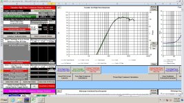
If I simulate a 160 mm wide baffle with a typical 5.5" woofer, I get a 4-pi response like this
View attachment 1448376
Here is a reasonable shelf filter to counteract that baffle step. A second order low-shelf of +6 dB at 275 Hz, Q=0.53
View attachment 1448377
View attachment 1448378
This is the filter that would work with an ideal 5.5" driver. Your woofers will have a response that is different, but this gives you an idea of what is reasonable.
Are you interested in going through the process of making near-field frequency response scans of each driver, then merging them to the time-windowed far-field response scans? This would give a quasi-anechoic response for each driver, and it would be a good way to start simulating the response. If you restrict yourself to only the on-axis response at this point, VituixCad is not too difficult to learn. Because your baffle shape and layout is already firmly defined, there is limited value in doing polar response scans... in other words, the directivity performance of this speaker is mostly fixed for this speaker, there is not much you can do to adjust it at this point. It is probably better to just focus on the on-axis performance and get that optimized first.
If you are interested in going down this path, you can start by making some near field scans of each driver.
- learn how to do them properly, import into VCad amd interpret them and learn that part of VCad
- learn how to use any directivity data in the crossover design
I will do near-field sweeps this weekend.
Why so low and specifically 200Hz?When you measure the tweeter, I suggest that you should sweep starting at 200hz or lower. If you want, you can use a cap for protection. In fact, the cap could be a permanent part of the speaker, and protect the tweeter from all sorts of potential future problems.
When I measure tweeters, I start the sweep at 500 Hz. I say "sweep", but I use the Arta option of PN-noise, a periodic pink noise signal, with 4 (sometimes 6) cycle averaging.
I am curious about the advantages of going as low as 200 Hz for a tweeter FR scan. I am talking about conventional tweeters with an Fs of 600 Hz or greater...
I am curious about the advantages of going as low as 200 Hz for a tweeter FR scan. I am talking about conventional tweeters with an Fs of 600 Hz or greater...

Mostly to confirm it's rolling off all the way down. Also, I suspect other issues, but it's mostly what I'm used to doing.
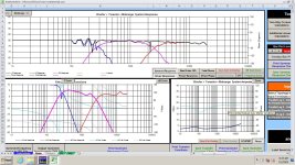
This is from a speaker measurement of mine, not this project. I know it's not critical that far below the x-over, but I'd rather be able to look at it anyway. Note the target overlay is the green line. In this case a LR4 at 2k.
This is from a speaker measurement of mine, not this project. I know it's not critical that far below the x-over, but I'd rather be able to look at it anyway. Note the target overlay is the green line. In this case a LR4 at 2k.
Attachments
Last edited:
Here's what I came up with. I need to use the same woofer file that you guys are using. This one sure looks different down low. Like others have said, the measurements on the woofer are not great. Three ways are tricky down low. I think the other measurements on axis measurements were OK.
I'll not post the filters at this point, but there would be no real surprises if I did. Not being secretive. I can if someone really wants to see them.
I'll not post the filters at this point, but there would be no real surprises if I did. Not being secretive. I can if someone really wants to see them.
Attachments
Hi,
I simulated the NF measurement for W and M and that's what I got.
Enclosure volume for both woofers is 10L and 1.5L for mid. Diffraction files and ctc distances are guesstimated from the pictures in the thread.
All FR exports are gated: I just followed the instructions given by Kimmo in his pdf.
The folder containing the export files and the VC project is attached.
Attachments
Perhaps sweeping starting at 200hz is not a great idea for many situations.
Mods please remove the suggestion.
. It's common for me to start with a cap on the tweeter for the first sweep, although I have done so without. . That would almost be a requirement for some tweeters. This wave-guide tweeter probably would be fine, but no reason to take unnecessary risks.
Mods please remove the suggestion.
. It's common for me to start with a cap on the tweeter for the first sweep, although I have done so without. . That would almost be a requirement for some tweeters. This wave-guide tweeter probably would be fine, but no reason to take unnecessary risks.
@temp25 I understand why you start at 200 Hz. I somewhat forgot how sine sweeps work.
When I use ARTA, in the PN-noise option, I can set the low frequency cutoff to some value, say 500 Hz. The noise signal is rolled off at 500 Hz, but there is still usable resolution down to at least 2 octaves below that, and the ARTA software compensates the recovered signal so that the response is equivalent to a full wide band signal.
So in my case, setting the lower limit at 500 Hz still allows me to capture the very low range of the tweeter, down to almost 100 Hz.
I lost sight of the fact that with a sine sweep, the lower limit of the sweep is the actual lower limit of the measurement...
As far as protection of the tweeter, I think it is fine to use a wide band sweep, starting at 200 Hz, as long as the voltage is kept moderate. I know some people on this forum to frequency response scans of tweeters from 20-20 k, and if the drive voltage is kept below 0.1 Vrms, it does not seem to do any harm to the tweeter. Back when I used the OmniMic, this is what I did.
j.
I measure out to 90 degrees at 10 degree intervals.I think this is sensible at this stage. I will definitely do nearfield soon.
I will then try to do new and better far field either outdoor, in a very large room or even find a better option. Already started working on these.
So, for the 'good far flied', do I just do a full 0 to 180 degrees sweeps at 10 deg intervals, horizontally? Do I need to do anything else? Is this what is meant by 'the full polar'? Can you help me to scope this 'good far filed' measurement?
I have a lazy Susan dolly with tape marks on it to make it faster. They're like 10 or 20 bucks on Amazon
I still think your best bet is clamping a pole to you balcony railing and pointing the speaker out into the air.
But barring that, read up on near field measurement. You'll want to get some measurements this way for bass anyways.
I've accidentally swept domes from 20Hz at quite high levels and they've survived. I agree that starting low is desirable or even conveniently consistent. A person has to learn and take care and may200hz
The capacitor option is good. It can be reverse engineered out of the measurement if that's necessary or changed in value. It can also be left in circuit and worked around to achieve any response.
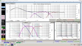
I crossed the mid to the woofer low on this sim. I used Shadowplays woofer file, which showed no roll-off. Knowing the actual roll-off at 80hz, I added boost, so it looks really loud below 100hz, but with roll-off it should be nice.
I see his sim rolls off. I must have grabbed the wrong file.
I see his sim rolls off. I must have grabbed the wrong file.
Attachments
This weekend I plan to do:
1. A set of nearfield measurements. Question is how to do the woofers, as there are two in the same cavity. There seem to be three options
a. measure one at 2cm and cover the other
b. measure one at 2cm and not cover the other
c. measure both (between the woofers vertcally) at say 20cm. Shall the mic point at the middle (i.e. horizontall) or at the centre of one of the drivers in this case (i.e a bit up)?
Any of these preferred or not worth it? I can easily do all three if it helps. Any other methods?
2. Try to get slightly better far field measurements. Still indoors in the same room, but shorter mic distance (1m instead of 2m), which will hopefully improve the quality a little. A bit later I will re-do these outdoors or in a large space and at a tall position or try to find an even better option.
I will then import into VCad, attempt to merge near and far field, model a few set up options, program in HFD, tweak and measure full speaker in room.
There is also the last piece of hardware to install - bottom ballast.
Let me understand this. Normally, in HFD, I would add two LR2 highpass/lowpass filters on both sides for form a LR4 crossover - which keeps the phase. Say HF and MF.Step 1. The Hypex filter designer will let you dial in any desired delay to time align those drivers perfectly. Looking at the directivity, distortion, max SPL of the drivers at their low frequency limit and break up at the high end you can select the crossover frequencies. Step 2. I recommend using a Linkwitz transform (asymmetric second order shelf filter) to form half of a fourth order high pass filter for the tweeter and midrange. This is a really neat solution that is made possible using the DSP. The Linkwitz transform can be configured to produce a second order high pass with Q = .707 at the crossover frequency. Step 3. Then a second Q = 0.707 second order high pass filter is cascaded with it to produce the very effective Linkwitz Reilly fourth order crossover filter used by many designers. Using this method perfectly cancels the natural highpass roll off and phase response of the driver and produces a phase perfect LR 4th order crossover. I may be wrong, but I believe this method is my innovation as I've not seen it talked about else where. Step 4. Set the power limiting for each driver to make the system "party proof" so that guy holding the beer can't hurt anything.
The above suggestion is to add a LT filter (asymmetric high/low shelf) on top of a single LR2 filter to form the crossover and keep the phase. Can you explain how the second approach works and its benefits?
Big thank you for teaching me to import driver measurement into VCAD. A bit of a breakthrough in finally using it with your help. Would appreciate if you help me to do the merge of nearfield once I have it.Let's just start with what you have right now.
Open your initial measurements in REW. Label them like this:
Then select file->export->export all measurements as text. Then make the pop up look like this:
Save to a folder of your choosing. Recommend something like "initial FRD" or whatever you'll remember. Normally I'd include phase, but I don't know what going on with this measurement, so we're just going to ignore it.
Next post we'll go over importing into VCAD
I can try. I haven't messed with nearfield anywhere near as much.
There is a thread over at ASR called "How to make quasi-anechoic speaker measurements/spinoramas with REW and VituixCAD"
The first bunch of posts is a step by step, and goes into the nearfield merging.
As far as how to do the woofers, you can probably measure them individually and then merge them, then add the baffle step to the merged output.
I suspect you can also measure one, then bump the whole thing up 6db and then baffle step it and get the same result.
I'm not confident at all in my thoughts on the woofer measurements though. Experiment I guess.
Have a look at the document linked in #443. Read it at least 3 (4, 5, 6 ...) times and try to follow it very accurately once you merge the near/farfield measurements.help me to do the merge of nearfield once I have it
It took me some time to understand the steps!
Measure NF response (mic at 5mm from dust cup) and export the file. If two woofers have shared box, feed signal to both woofers and isolate (not brake) the other (which is not under test) with pillow to prevent midrange frequencies going to mic too much. You do not have a port so you don't have to measure it.Big thank you for teaching me to import driver measurement into VCAD. A bit of a breakthrough in finally using it with your help. Would appreciate if you help me to do the merge of nearfield once I have it.
Design your baffle in diffraction tool: use rouded edge as you have facets.
Export diff. resp. at 10m and 1m
Measure farfield and export the files
Open Merger tool and load your FR
Adjust the LF part level, choose a merging frequency (typically around 400Hz) and export your files (change your extension).
These all sound logical to me.As far as how to do the woofers, you can probably measure them individually and then merge them, then add the baffle step to the merged output.
I suspect you can also measure one, then bump the whole thing up 6db and then baffle step it and get the same result.
A few points to clarify.Measure NF response (mic at 5mm from dust cup) and export the file. If two woofers have shared box, feed signal to both woofers and isolate (not brake) the other (which is not under test) with pillow to prevent midrange frequencies going to mic too much. You do not have a port so you don't have to measure it.
Design your baffle in diffraction tool: use rouded edge as you have facets.
Export diff. resp. at 10m and 1m
Measure farfield and export the files
Open Merger tool and load your FR
Adjust the LF part level, choose a merging frequency (typically around 400Hz) and export your files (change your extension).
View attachment 1449442
- 5mm ok for tweeter and mid, but the woofers have 20mm+ Xmech, so I will do 25mm distance, just in case.
- I got the point about covering the 2nd woofer from the original post. However got confused by the 'to prevent midrange frequencies going to mic too much'. Why midrange? the midrange channel will be muted. Do you mean mids from the 2nd woofer? if so, why the mids be a consern and not the highs or lows?
- Home
- Loudspeakers
- Multi-Way
- 3-way to active - Hypex FA253 - learning project