I wouldn't trust this set of measurements fully. The phase is crazy, I don't know what to make of it honestly. Probably just ignore it on this measurement set.
Get an initial setup if you like, but I'd get a plan to do a measurement set outside, as high off the ground as you can manage.
The required shelf filter may be much lower than that.my baffle is 160mm so BSC f should be about 720Hz, right? 115/baffle width in m. that is way into the midrange
If I simulate a 160 mm wide baffle with a typical 5.5" woofer, I get a 4-pi response like this
Here is a reasonable shelf filter to counteract that baffle step. A second order low-shelf of +6 dB at 275 Hz, Q=0.53
This is the filter that would work with an ideal 5.5" driver. Your woofers will have a response that is different, but this gives you an idea of what is reasonable.
Are you interested in going through the process of making near-field frequency response scans of each driver, then merging them to the time-windowed far-field response scans? This would give a quasi-anechoic response for each driver, and it would be a good way to start simulating the response. If you restrict yourself to only the on-axis response at this point, VituixCad is not too difficult to learn. Because your baffle shape and layout is already firmly defined, there is limited value in doing polar response scans... in other words, the directivity performance of this speaker is mostly fixed for this speaker, there is not much you can do to adjust it at this point. It is probably better to just focus on the on-axis performance and get that optimized first.
If you are interested in going down this path, you can start by making some near field scans of each driver.

have a look at kimmo's instructions for measurmenets with REW:Measurements in room, mic 2m.
https://kimmosaunisto.net/Software/VituixCAD/VituixCAD_Measurement_REW.pdf
you need to do nearfield measurements of woofers and midrange to get somewhat meaningful pseudo-anechoic results.
Yes, will do the nearfield and try VCad. But want to learn how to do directivity in VCad. Also would like to make directivity map for my speaker. Would appreciate any support!
Let's just start with what you have right now.
Open your initial measurements in REW. Label them like this:


Then select file->export->export all measurements as text. Then make the pop up look like this:

Save to a folder of your choosing. Recommend something like "initial FRD" or whatever you'll remember. Normally I'd include phase, but I don't know what going on with this measurement, so we're just going to ignore it.
Next post we'll go over importing into VCAD
Open your initial measurements in REW. Label them like this:
Then select file->export->export all measurements as text. Then make the pop up look like this:
Save to a folder of your choosing. Recommend something like "initial FRD" or whatever you'll remember. Normally I'd include phase, but I don't know what going on with this measurement, so we're just going to ignore it.
Next post we'll go over importing into VCAD
When VCAD opens, it looks like this in the upper left corner:

Click on the Drivers tab.
You should see this:

Click on the space where is says driver #1 and re-name it to woofer
Then click on the open folder icon to load frequency response files.
While holding the control key, click on each of the woofer files, should look like this:

Click open. Ignore the warning about phase for now.
Then click on the plus icon (look up two pictures) to add another driver, change it's name to midrange and repeat. Keep doing this until you have this:

Next is building the crossover.
Click on the Drivers tab.
You should see this:
Click on the space where is says driver #1 and re-name it to woofer
Then click on the open folder icon to load frequency response files.
While holding the control key, click on each of the woofer files, should look like this:
Click open. Ignore the warning about phase for now.
Then click on the plus icon (look up two pictures) to add another driver, change it's name to midrange and repeat. Keep doing this until you have this:
Next is building the crossover.
I forgot this on import, at the bottom of the drivers tab, make sure you've selected 1/3 smoothing. The data we're dealing with is scketchy, no sense making it worse by correcting things that aren't real.

Click on the Crossover tab to get started. Below is a basic active crossover with no corrections. Each channel gets an active adjustment (amp) and a set of appropriate hi/lo passes.

When you click on a high or low pass entity, at the bottom of the window, you'll see the following:

For now, just set all of yours to linkwitz-riley and N4 (LR-4).
The basic crossover above should look like this in the simulation:

More to follow
Click on the Crossover tab to get started. Below is a basic active crossover with no corrections. Each channel gets an active adjustment (amp) and a set of appropriate hi/lo passes.
When you click on a high or low pass entity, at the bottom of the window, you'll see the following:
For now, just set all of yours to linkwitz-riley and N4 (LR-4).
The basic crossover above should look like this in the simulation:
More to follow
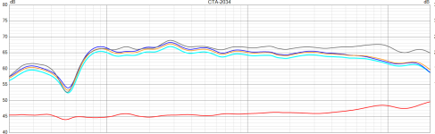
Ok, so now I'm going to start looking at both power response and the on axis response and see if we can easily smooth it out a bit. Don't go crazy, keep in mind our measurements stink.
Power response is the blue line (almost the same thing as estimated in room)

My first thought is the midrange response is peaky. This makes sense, the driver you've used has a rising response and fall off before the breakup. Our crossover only got rid of the breakup.
So I'm going to add a peaking filter of -2db, centered at 1146hz (put the cursor on the middle of the hump to figure that out) and use a Q of 2. I'm also going to increase the midrange volume up to -7db and lower the tweeter down to -9db


So now I'm reasonably happy with the midrange and tweeter for a first go at it.
Next we'll deal with the woofer
Power response is the blue line (almost the same thing as estimated in room)
My first thought is the midrange response is peaky. This makes sense, the driver you've used has a rising response and fall off before the breakup. Our crossover only got rid of the breakup.
So I'm going to add a peaking filter of -2db, centered at 1146hz (put the cursor on the middle of the hump to figure that out) and use a Q of 2. I'm also going to increase the midrange volume up to -7db and lower the tweeter down to -9db
So now I'm reasonably happy with the midrange and tweeter for a first go at it.
Next we'll deal with the woofer
With in room measurements, doing much with the bass is going to be a fool's errand. So the key here is do the minimum to get something workable for now, and then refine when you get better measurements. (Near-field and/or outside away from the ground.)
So our two big things to figure out are the linkwitz transform and the weird dip/rise that's going on between 100hz and the peak at 280hz.
Let's deal with the LT first, it should be easier, and we know that correction is real. A bass bump and the steep drop off is pretty characteristic of a high Q alignment, so I'm going to guess 70hz and 1.2 Q. If you feel confident at guessing your final volume you could go back to re-simulate the enclosure, but just looking at the response and making it look "about right" is probably just as accurate. LT is the squiggle symbol. I'm going to set my desired pole frequency and Q at 40hz, .707. See below.

The sim now looks like this:

Better, but I'm going to drop the midrange back down to -8db

So now the dip/rise thing is just that peak at 280hz.
This is moving the crossover down to 300hz:

So our two big things to figure out are the linkwitz transform and the weird dip/rise that's going on between 100hz and the peak at 280hz.
Let's deal with the LT first, it should be easier, and we know that correction is real. A bass bump and the steep drop off is pretty characteristic of a high Q alignment, so I'm going to guess 70hz and 1.2 Q. If you feel confident at guessing your final volume you could go back to re-simulate the enclosure, but just looking at the response and making it look "about right" is probably just as accurate. LT is the squiggle symbol. I'm going to set my desired pole frequency and Q at 40hz, .707. See below.
The sim now looks like this:
Better, but I'm going to drop the midrange back down to -8db
So now the dip/rise thing is just that peak at 280hz.
This is moving the crossover down to 300hz:
Attachments
I'm not sure playing with the remaining bump is worth it right now. If I flip the mid polarity you can see there's something odd with the crossover here. I'm not sure it's real.

But as an experiment, I'm going to add a peaking filter to the midrange below the crossover point. It's -15db, Q 10 at 256hz.


You can see here where it is and how narrow/deep. and what it does to the response. But again, I have no confidence it's real. I'd probably setup the filters without that last part. Measure, then add the weird notch filter and try again just to see what it looks like / sounds like.
And after all that, keep in mind, with indoor far field measurements, this is all a lie.
But it should be enough to get you started playing around and listening to the things you built.
But as an experiment, I'm going to add a peaking filter to the midrange below the crossover point. It's -15db, Q 10 at 256hz.
You can see here where it is and how narrow/deep. and what it does to the response. But again, I have no confidence it's real. I'd probably setup the filters without that last part. Measure, then add the weird notch filter and try again just to see what it looks like / sounds like.
And after all that, keep in mind, with indoor far field measurements, this is all a lie.
But it should be enough to get you started playing around and listening to the things you built.
I would add boost to the bass. The sealed f3 roll-off can be improved. My estimate is about 10dB at 40hz with a Q of .6 or so, but it depends on the box Q. . That should hopefully get the f3 down to about 40hz. Keep an eye on excursion!
I was going to offer old school suggestions on filters, but Busdriver02 pretty much came up with the same thing. (First part of post #448 only. Not the part where he altered the bass. ) , But I didn't use a computer sim. I just looked at the measurements. I'd lower the mid gain a couple more dB than he suggested, but regardless, your going to measure afterwards anyway, so....
If you start with his suggestion, and add my bass boost, or his, I think you will be in the ballpark, or ballpark parking lot.
Put the speaker on stands horizontally if it will get the woofers farther away from floor and ceiling.
Make a new sweep of the whole speaker from 100hz to 20k No need to give the woofers a workout. See what the gated measurements look like. I'd put tweeter, and "the rest" on the same graph, and look at the roll-offs. The rest meaning the summed woofers and mid. Treat the mid and woofer like one driver. No need to look at the woofers alone. ( Not yet anyway. ) Mostly look at 300hz and above. I'd EQ for flat and level, but some like a tilt. You can do either. I'd start flat myself.
Next move the mic to approximately half way between the mid, and woofers, and about 12" from the baffle. Turn down the speaker volume about 6dB, or so. Make a sweep from 60hz to 1k. . Then flip polarity on the woofer, and make another. Should be a smooth dip at the x-over. I know AllenB will say this doesn't matter. Perhaps he's right, but it will confirm what's going on, so I say it can't hurt to look. All measurements are good practice anyway. Don't forget to flip polarity back.
Next... Play some familiar music, and enjoy / be critical / relax. Future x-overs will likely improve. Don't obsess over perfection. (Yet)
Last edited:
I'm unfamiliar with the gain limits of your setup. So keep that in mind.
The sealed woofer f3 is about 80hz. If you ultimately want to go deeper than 40hz, without a sub, I would go ahead and assume there will be a lot of boost. It makes sense to me that you might as well boost all of the woofers response a lot, and then reduce the woofer response above 40hz. So maybe add 5dB of woofer gain, and subtract 5 dB of mid-range gain as a starting point. (Rather than just reducing the mid level by 10dB. )
Then start filtering down everything above 40hz at 12dB an octave to 80hz with a shelf filter. That, I think, would counteract the woofers natural roll-off below 80H, and there would still be the option of additional boost below 40hz. Above 80hz would be flat till you add the woofer low-pass at 400hz.
I could draw a picture if needed, and it might seem more logical. Obviously you don't want to clip inputs, so more thought might be needed.
Also some Sims showing woofer excursion, and SPL limits may be helpful. My software confuses the issue on the power needed, but it looked like 100dB at 40hz was possible. I'm going from memory, so that may be inaccurate. I did the sim last night. The box Q will play a roll. I'm hoping that you might be below a Q of .5. The lower the Q, the deeper you can go with less boost.
Last edited:
you have shorted the input. there is a line across the signal sourceonly individual filters.
Drivers added to VCad and basic filters/gains added. Does not look the same as in @Busdriver02 posts

smoothed all drivers but still graphs are different. Must be more settings I have missed. How do I see power response? with DI curve under it.

Last edited:
That looks about the same to me. If you can now measure the speaker as I posted previously, you can compare to what you have here in the sim. Low frequencies are hard to measure, but 300hz and up should be relatively easy.
Woofer could benefit from a mild notch at about 280hz. Maybe 2dB.
Woofer could benefit from a mild notch at about 280hz. Maybe 2dB.
- Home
- Loudspeakers
- Multi-Way
- 3-way to active - Hypex FA253 - learning project