IIts not really classical NXT. I found a paper, who describes the effect. At least i think so:
https://www.google.com/url?sa=t&source=web&rct=j&url=http://orca.cf.ac.uk/56177/&ved=2ahUKEwjnybCL3pzvAhVLyaQKHQU7A-kQFjAAegQIARAC&usg=AOvVaw2z7M-MlocFrYL3zXvuEGOJ
I read also this, but Google missed probably some details.
Do you know why I not see measurement images on page 3 of this topic, are they missing or I need to have account?
On page 3 i dont see any images, too. The thread is 10 years old, so probably the image-provider don't show them. On page 2 i can see all images.
I have read the study one year ago, so i dont remember exactly the site. But i remember, that at low frequencys the panel dont breaks up in NXT, but the whole baffle moves completly as a whole forward and backward. To stimulate this you need a exciter array.
My interpretation of the MoDiPo is, that near the resonance frequency of the SPP-250 with the high qts it works for this specific frequency area like a exciter.
It would be very interesting to explore this more.
With your H-frame and 2xSPP-250 the cone resonance will be at about 25 Hz, but peak is on 40 Hz.
This why I am interested in impedance measurement.
Same is also in original MoDiPo built, impedance resonance is at 25 Hz but SPL peak is at 40 Hz.
This why I am interested in impedance measurement.
Same is also in original MoDiPo built, impedance resonance is at 25 Hz but SPL peak is at 40 Hz.
Last edited:
My German is ganz schlecht, but room resonance is most likely the reason for bump below 30Hz. If it were the box "NXT", spl shoud be minimal at those frequencies (but could appear in nearfield measurement done at modest spl)
My guess is that measurement methodology is suspicious. Rudolf asked for reproducibility too... Since 2007-11 we have learned a lot about that.
My guess is that measurement methodology is suspicious. Rudolf asked for reproducibility too... Since 2007-11 we have learned a lot about that.
I have measured nearfield LF like in this photo:
After that i merged the nearfield-measurement for LF with the higher frequency part of the 1m measurement.
That is not the correct way to do it.
The nearfield LF measurement does not capture or include the interaction with the other (front or back) source of the H-frame.
The proper way to do it is:
1. synthesize dipole (your H-frame) LF response:
A. obtain front and rear nearfield by either:
a. measuring front and rear at opening, or
b. measure front only and create rear by inverting the phase response of the front measured data.
B. Measure the separation distance between front and rear sources of the H-frame
C. Sum the measurements to properly represent the dipole source:
a. Add a delay to the rear measurement equal to the speed of sound divided by the separation distance
b. Sum the front and rear data
At this point all you have is the synthesized LF response of your dipole.
If you will be crossing over above 200-300Hz, make a far-field measurement and sum that with your synthesized LF response.
There are some details I have omitted, like how to set the proper level when summing, how to sum responses, how to add in the delay, etc.
This is saying the same thing as what kaameelis posted, above.
With your H-frame and 2xSPP-250 the cone resonance will be at about 25 Hz, but peak is on 40 Hz.
This why I am interested in impedance measurement.
Same is also in original MoDiPo built, impedance resonance is at 25 Hz but SPL peak is at 40 Hz.
Hi kaameelis,
My have a peak at 40 Hz. But the MoDiPo have a peak from 20-40 Hz from the baffle. Dont look on one graph only. You have to compare the estimated FR with the measured one. They got +10dm from 20-40 Hz.
I will take a measurement on my balcony tommorow. If it cames from the room, i should see a big difference at 40 Hz.
🙂
Rudolf asked for reproducibility too... Since 2007-11 we have learned a lot about that.
Hi Jahuzi,
yes he asked for it and got the answer, that it is reproducable.
Best regards, Tomas
That is not the correct way to do it.
The nearfield LF measurement does not capture or include the interaction with the other (front or back) source of the H-frame.
The proper way to do it is:
1. synthesize dipole (your H-frame) LF response:
A. obtain front and rear nearfield by either:
a. measuring front and rear at opening, or
b. measure front only and create rear by inverting the phase response of the front measured data.
B. Measure the separation distance between front and rear sources of the H-frame
C. Sum the measurements to properly represent the dipole source:
a. Add a delay to the rear measurement equal to the speed of sound divided by the separation distance
b. Sum the front and rear data
At this point all you have is the synthesized LF response of your dipole.
If you will be crossing over above 200-300Hz, make a far-field measurement and sum that with your synthesized LF response.
There are some details I have omitted, like how to set the proper level when summing, how to sum responses, how to add in the delay, etc.
This is saying the same thing as what kaameelis posted, above.
Hi CharlieLaub,
probably there was something missed in the quotation, or my answer was not complete (sorry for my bad english). I did it exactly thi way:
measure a dipole
I know, its only a approximation, but i think in the very LF part it will be good enough. On the other Hand, if i make a measurement like you recommend, where do you measure exactly on the backside? On the end of the H-Frame? Or 2cm behind the magnet?
I can make this measurement...
To all:
Probably i have a mistake in my measurement. Probably the ModiPo measuremts arent correct. But Probably we fall in a trap right now: theory induced blindness.
It can be in both way, in measurements can be mistake or in theory can be mistake and theory did not count all parameters.
I understand Charlie's point is that measurement need to be done not near to speaker cone but near to H-frame opening. In your case there is difference about 100 mm.
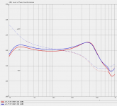
But I put in Akabak simulation one measurement point on 10 mm distance from cone center, result was nearly flat line from dipole peak to 30 Hz, so Akabak simulation did not predict 40 Hz peak in near cone measurements. On image blue line is 10 mm and red is 30 mm from upper cone. My initial simulation measurement points where 1 m from middle point of cones.
One point more. All resonances (peaks or holes) in SPL curve what are related to speaker cone movements will left some sign also in speaker impedance curve. In original MoDiPo impedance curve they are missing or at least not visible, maybe filtered out.
I understand Charlie's point is that measurement need to be done not near to speaker cone but near to H-frame opening. In your case there is difference about 100 mm.
But I put in Akabak simulation one measurement point on 10 mm distance from cone center, result was nearly flat line from dipole peak to 30 Hz, so Akabak simulation did not predict 40 Hz peak in near cone measurements. On image blue line is 10 mm and red is 30 mm from upper cone. My initial simulation measurement points where 1 m from middle point of cones.
One point more. All resonances (peaks or holes) in SPL curve what are related to speaker cone movements will left some sign also in speaker impedance curve. In original MoDiPo impedance curve they are missing or at least not visible, maybe filtered out.
Attachments
It can be in both way, in measurements can be mistake or in theory can be mistake and theory did not count all parameters.
I understand Charlie's point is that measurement need to be done not near to speaker cone but near to H-frame opening. In your case there is difference about 100 mm.
But I put in Akabak simulation one measurement point on 10 mm distance from cone center, result was nearly flat line from dipole peak to 30 Hz, so Akabak simulation did not predict 40 Hz peak in near cone measurements. On image blue line is 10 mm and red is 30 mm from upper cone. My initial simulation measurement points where 1 m from middle point of cones.
One point more. All resonances (peaks or holes) in SPL curve what are related to speaker cone movements will left some sign also in speaker impedance curve. In original MoDiPo impedance curve they are missing or at least not visible, maybe filtered out.
Kaameelis,
very good! Yes i did not measure near the H-Frame opening. I meaasured 10-15mm on distance to the cone. it's about 7cm from the H-Frame opening away. Tomorrow i will test it.
Regarding the study you can read the summery on the first pages. It gives you some ideas... If its from baffle movement you dont see any sign in the impedance curve (i think so).
Hmm.... from hearing i have to say, that i have only needed a PEQ Sum of 13db from LF to the peak at 400Hz. But i am not familar with dipol-bass so high likely its not correct....
If cone movement is causing baffle movement and resonance, then some, at least small sign must be present in impedance curve.
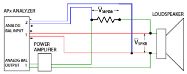
I have a Tascam us-144mkii soundcard a multimeter. Can i make impadance measuremt with it? Its the first time that i make a impedance measurement...
Yes you can. US-144MKII had headphone output.
Use headphone output of one channel. US-144MKII had balanced inputs, important is to connect "-" contacts of inputs (line inputs 14 and 16 in manual) together with headphone output ground. Resistor musty be about 100 ohm, but with precisely know value.
Use headphone output of one channel. US-144MKII had balanced inputs, important is to connect "-" contacts of inputs (line inputs 14 and 16 in manual) together with headphone output ground. Resistor musty be about 100 ohm, but with precisely know value.
Hi,
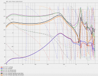
sorry for the delay! I took some measurements yesterday (all measurements not spl calibrated):
First of all the H-Frame (this time) 1 cm from the opening:

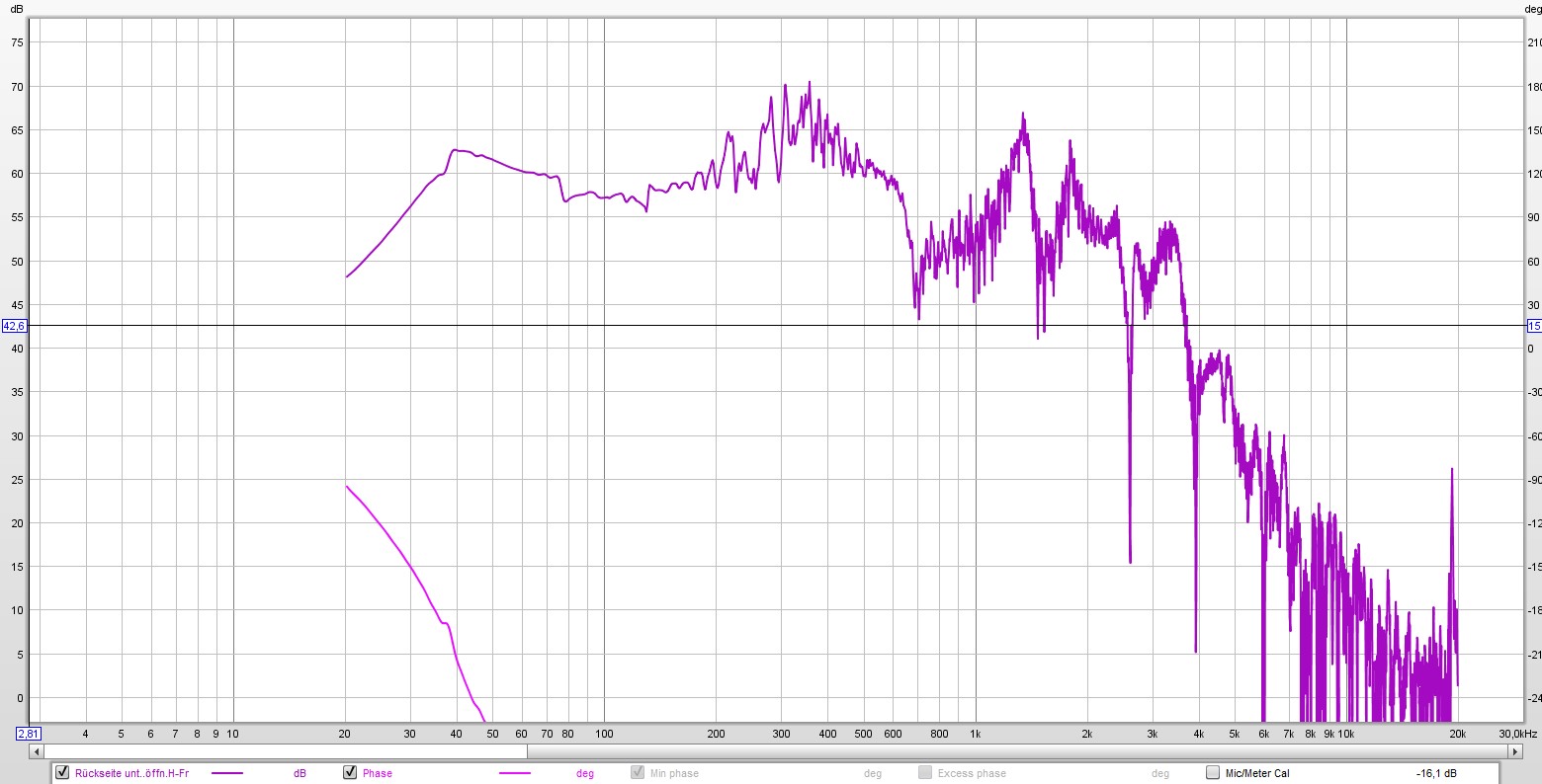
Now the Backside:
The hext measurement is on the doorstep to the open balcony.:

In my eyes, the room-mode at 40 Hz gived an additionaly 2db and a stronger db loss under 40HZ in the nearfieldmesurement. But overall there is still a strong Bassresponse from 35-45 Hz. If i hold my fingers on the MDF-Baffle i can recognize vibrations.
Best regards,
Tomas
sorry for the delay! I took some measurements yesterday (all measurements not spl calibrated):
First of all the H-Frame (this time) 1 cm from the opening:
Now the Backside:
The hext measurement is on the doorstep to the open balcony.:
In my eyes, the room-mode at 40 Hz gived an additionaly 2db and a stronger db loss under 40HZ in the nearfieldmesurement. But overall there is still a strong Bassresponse from 35-45 Hz. If i hold my fingers on the MDF-Baffle i can recognize vibrations.
Best regards,
Tomas
Hi i made a soundcard calibration. The bass response measures even better now (+1,5db at 30Hz ). And i have seen that the merged respone from far field and nearfield at was to conservative. I will make some additional tests in the future...
I see now, what some of you said about 4" drivers in Dipole-configuration. If crossed at about 300Hz, i get high distortion in the 400-700Hz area. The w4-1320SJ is a very nice driver, but i am looking for alternatives with a better distortion-profile. The w4-1320sj has about 0,8% k3 @ 500Hz in Dipole configutration at 90db.
In enclosure you get the same distortion @ 500Hz with 96db. So this is much better.
Its much easier to find a 5" with suitable distortion-profile. My goal is to get a 4" with K3<0,3% @ 95db, but better would be @ 100db. (for normal enclosure..)
Any ideas?
I could combine 4 TC9FD in D'Appolito configuration, but then i will have other problems off axis...
Greetings, Tomas
). And i have seen that the merged respone from far field and nearfield at was to conservative. I will make some additional tests in the future...I see now, what some of you said about 4" drivers in Dipole-configuration. If crossed at about 300Hz, i get high distortion in the 400-700Hz area. The w4-1320SJ is a very nice driver, but i am looking for alternatives with a better distortion-profile. The w4-1320sj has about 0,8% k3 @ 500Hz in Dipole configutration at 90db.
In enclosure you get the same distortion @ 500Hz with 96db. So this is much better.
Its much easier to find a 5" with suitable distortion-profile. My goal is to get a 4" with K3<0,3% @ 95db, but better would be @ 100db. (for normal enclosure..)
Any ideas?
I could combine 4 TC9FD in D'Appolito configuration, but then i will have other problems off axis...
Greetings, Tomas
Yes you can. US-144MKII had headphone output.
Use headphone output of one channel. US-144MKII had balanced inputs, important is to connect "-" contacts of inputs (line inputs 14 and 16 in manual) together with headphone output ground. Resistor musty be about 100 ohm, but with precisely know value.
I have still not done this. Sorry for the delay. I made some progress with my active 3 way dipole at other points like distortion baffle size or no baffle etc...
I dont have headphone jacks at home. If i understood you and the rew website right i need 3 headphone jacks:
Is this ok 3 times:
Boutique Haut-parleurs & Audio DIY
?
and a 100 ohm resistor:
Is this ok?
Boutique Haut-parleurs & Audio DIY
Better is to use TRS plugs (stereo), as US-144 had balanced inputs, on output you can use only one channel.
Resistor can be also for lower power, 1 W or even smaller as current is small, about 50 mA and power about 0.25 W.
Resistor can be also for lower power, 1 W or even smaller as current is small, about 50 mA and power about 0.25 W.
Last edited:
Its first time i buy headphone jacks, so soryy for this questions😕
This one?
Boutique Haut-parleurs & Audio DIY
Regarding the resistors. I have some small standart resistor at home. Sure, i wil find a suitable value...
This one?
Boutique Haut-parleurs & Audio DIY
Regarding the resistors. I have some small standart resistor at home. Sure, i wil find a suitable value...
- Home
- Loudspeakers
- Multi-Way
- 3-Way OB - get the best out