Thank you all . I tried allot with xsim to find the right XO.
I decide to switch to active crossover with op amp
which is much better and easy .l have knoledge for that
just have to learn how calibrate the phase .
I decide to switch to active crossover with op amp
which is much better and easy .l have knoledge for that
just have to learn how calibrate the phase .
Last edited:
Aha, you make it too easy and one forgets how to do the hard part 😉
We can help. The way to do it is different for each kind of setup, so..
We can help. The way to do it is different for each kind of setup, so..
I need to decide which is the best schematic for 24 db 3 way active XO
I can test it with LTspice program .
The problem is how I test it with my specific elements .
I can test it with LTspice program .
The problem is how I test it with my specific elements .
Ok, will this be an analogue active design?
If you can measure and find where the driver is at, then compare it to where you want it to be then you can find the difference and make your circuit do this.
If you can measure and find where the driver is at, then compare it to where you want it to be then you can find the difference and make your circuit do this.
Most people don't realize that designing an active crossover (analogue or digital doesn't matter), involves more or less the same approach as designing a passive crossover: measurement.
Without that you need to make assumptions (for example where the sound originates in every driver), and you can get only in the ballpark. IMHO a simulation is essential in deciding if a design can be successful or not, but shouldn't be the only tool to make the design.
Ralf
Without that you need to make assumptions (for example where the sound originates in every driver), and you can get only in the ballpark. IMHO a simulation is essential in deciding if a design can be successful or not, but shouldn't be the only tool to make the design.
Ralf
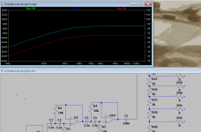
Here is famous example about 3 way active crossover
https://www.eeweb.com/electronic-crossover-with-3-way-output/
At the end of each filter he put a 10k trimmer for adjustment .
I tried to simulate the trimmer as a pot and it very very impedance dependable
Each test I put one ground to the 8 ohm resistor where I would like to test .
for more detail down load the project , am I doing something wrong ?
Attachments
Could you please explain how I take the impedance drive at each point ?.Ok, will this be an analogue active design?
If you can measure and find where the driver is at, then compare it to where you want it to be then you can find the difference and make your circuit do this.
I could see with XSIM just need to know what configuration I has to do .
And how to calculate it with the XO in LTSPICE .
Yes I am going to use 3 amplifier , One strong for bass , and for mid and tweeter chip digital amplifier .
I have got preamplifier to control the input .
I have got preamplifier to control the input .
What is the problem?I tried to simulate the trimmer as a pot and it very very impedance dependable
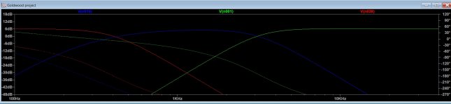
With the difference of the position of the trimmer , there is change in FR and phase .we have to know what impendence has the driver at the cut off . and of course how the phase will act .
This is how we test HPF\ BAND PASS \ LPF at the trimmer , when set to maximum 10K with no 8 ohm resistor connected to ground .
Attachments
Last edited:
It's unclear what you are trying to show with only one trace per band..
Why an 8 ohm resistor? You can't reasonably expect to drive a speaker with a 10k pot at the source.
Why an 8 ohm resistor? You can't reasonably expect to drive a speaker with a 10k pot at the source.
The XO is ok up to the "driver" 8 ohm resistor .instead of resistor . what is the right way to simulate the driver in LTspice ?
I guess I'd stop at the input impedance to the power amp. Since this will be a buffer there's no benefit to simulating the speaker.
Right I forgot we connect the active XO to the amplifier not direct to the driver 😱
The input impedance of the amplifier is probably about ~100k
So the trimmer simulation should look like that and to put the ground where we want the adjustment .
The input impedance of the amplifier is probably about ~100k
So the trimmer simulation should look like that and to put the ground where we want the adjustment .
Attachments

Last edited:
Actualy the XO is fine no need to change something there .
off course the drivers isn't equal with there phase .
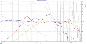
Here is picture of the drivers phase without any filters
The cut off FR of the active XO is 400HZ and 3KHZ .
At this points the difference , in the phase between bass mid is ~ +30... +60 degree toward the woofer .
Mid-tweeter about a +120 toward the mid .
If I get it right , to do the adjustment we have to minus woofer phase or to add midrange phase , in the XO , same trick to mid \tweeter ?
off course the drivers isn't equal with there phase .
Here is picture of the drivers phase without any filters
The cut off FR of the active XO is 400HZ and 3KHZ .
At this points the difference , in the phase between bass mid is ~ +30... +60 degree toward the woofer .
Mid-tweeter about a +120 toward the mid .
If I get it right , to do the adjustment we have to minus woofer phase or to add midrange phase , in the XO , same trick to mid \tweeter ?
Attachments
Last edited:
It is possible to do it this way but there are a number of other ways you can do it. Have you considered using speaker design software that can apply standard filters.. then you can go ahead and build those filters?
Yes what will be good software to speakers design ?
Anyway I thought it will be good idea to use oscilloscope to measure the phase in real time .
Just need to learn the calculation the cut off FR in active XO , and how to set the phase , I will read about it .
Anyway I thought it will be good idea to use oscilloscope to measure the phase in real time .
Just need to learn the calculation the cut off FR in active XO , and how to set the phase , I will read about it .
- Home
- Loudspeakers
- Multi-Way
- 3 way crossover design advices