Hi All,
I wonder if I might add a few observations.
No output biasing-drive arrangements are shown, and this will have a major influence.
If base to base biasing is floating wrt the emitter centre line then any degree of low level non-crossover class-A operation cannot be guaranteed at all instants, especially with fast VAS-CCS drive.
Type 'A' will operate more naturally with less need for closed loop stabilisation than 'B' or 'C', so I can understand Lumanauw's observations.
Only 'B' provides a fast (but sharply discontinuous if capacitor optimised) class-AB pull down capability.
In 'C' there is a trade of phase for gain; ie. easier to drive and better damping figure, but more (dynamic load induced) hf phase shift within a closed loop, unless resistors are kept very low as Kanwar suggests.
________________________________________________________________
PB2 asks about driver emitter resistors connected to the opposite rail. This is a very good idea, BUT, unless these are split and capacitor bootstrapped to the output terminal they cause an opposing current peak in the 'off' driver at maximum amplitude, and this can actually increase odd harmonic distortion.
Cheers ........... Graham.
Graham Maynard said:Hi All,
I wonder if I might add a few observations.
No output biasing-drive arrangements are shown, and this will have a major influence.
If base to base biasing is floating wrt the emitter centre line then any degree of low level non-crossover class-A operation cannot be guaranteed at all instants, especially with fast VAS-CCS drive.
Type 'A' will operate more naturally with less need for closed loop stabilisation than 'B' or 'C', so I can understand Lumanauw's observations.
Only 'B' provides a fast (but sharply discontinuous if capacitor optimised) class-AB pull down capability.
In 'C' there is a trade of phase for gain; ie. easier to drive and better damping figure, but more (dynamic load induced) hf phase shift within a closed loop, unless resistors are kept very low as Kanwar suggests.
________________________________________________________________
PB2 asks about driver emitter resistors connected to the opposite rail. This is a very good idea, BUT, unless these are split and capacitor bootstrapped to the output terminal they cause an opposing current peak in the 'off' driver at maximum amplitude, and this can actually increase odd harmonic distortion.
Cheers ........... Graham.
Graham,
what do You think about the combination of B and C? Common emitter resistor keeps the drivers in class A, and B-E resistors help to keep the better damping factor. Or is it wrong way to try?
sajti
Mr. John Curl uses A too in Parasound amp.
Why is that I found many things that is suggested by Doug Self works in contrary? His book is good and must read, but the recomendations doesn't always sounds good.
Why is that I found many things that is suggested by Doug Self works in contrary? His book is good and must read, but the recomendations doesn't always sounds good.
lumanauw said:Why is that I found many things that is suggested by Doug Self works in contrary? His book is good and must read, but the recomendations doesn't always sounds good.
Hi Lumanauw
You are a wise guy!...😉
I feel the same...but many people believe in everything they read...even in the Net.
Hi all,
Nice to see the thread accellerating! 😎
Upupa Epops
.)And whatabout combination A + B ?
Has the "development department" anything to report? 😉
hienrich
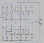
Interesting comments especially regarding the C type, Graham Maynard seem to have similar feelings about his latest amplifier design, as the Class-AABB output stage reminds partially about the C type shown in my schematic. (But he use also two stages in parallel with some slight bias difference)
PB2
No speciall reason, actually it didn't come to my mind, but when mentioning this i have thought about this too before.
The problem as I see it is a varying current biasing along the allternating signal amlified.
Say we have a positive output signal reaching top level of the amplifier (eg. the rail limiting), the upper output transistor have a huge current biasing at it's base that want to pull it down by the resistor all the way to the negative rail. But the opposite (lower output) transistor have a very weak biasing cloes to the positive rail making it slow.
If we assume there is huge bass signal offsetting the outputstage but at the same time a high frequent signal from let say the cymbal, at this point the high frequent signal is treated by two output transistors with huge different biasing at this point. But if we have a capacitor between then it's a bit different thing....
(edit: i see that Graham allready treated your answer, but here is my version anyhow.)
BTW I wellcome other types of outputstages to be discussed here!
Regards Michael
Nice to see the thread accellerating! 😎
Upupa Epops
.)And whatabout combination A + B ?
Has the "development department" anything to report? 😉
hienrich
Interesting comments especially regarding the C type, Graham Maynard seem to have similar feelings about his latest amplifier design, as the Class-AABB output stage reminds partially about the C type shown in my schematic. (But he use also two stages in parallel with some slight bias difference)
PB2
No speciall reason, actually it didn't come to my mind, but when mentioning this i have thought about this too before.
The problem as I see it is a varying current biasing along the allternating signal amlified.
Say we have a positive output signal reaching top level of the amplifier (eg. the rail limiting), the upper output transistor have a huge current biasing at it's base that want to pull it down by the resistor all the way to the negative rail. But the opposite (lower output) transistor have a very weak biasing cloes to the positive rail making it slow.
If we assume there is huge bass signal offsetting the outputstage but at the same time a high frequent signal from let say the cymbal, at this point the high frequent signal is treated by two output transistors with huge different biasing at this point. But if we have a capacitor between then it's a bit different thing....
(edit: i see that Graham allready treated your answer, but here is my version anyhow.)
BTW I wellcome other types of outputstages to be discussed here!
Regards Michael
lumanauw said:Mr. John Curl uses A too in Parasound amp.
Why is that I found many things that is suggested by Doug Self works in contrary? His book is good and must read, but the recomendations doesn't always sounds good.
I agree. 😀
I have a lot of respect for Curl and self, but they are on the other camp. I am on Nelson's and Dan D's camp which care more about listening than measuring. Nothing wrong with either, just like tea and coffee......
SATJI: You say the MJE1503X likes a lot of bias (I took that as an absolute statement) and then wondered why you like it biased so low in a "pre" driver position....
K-amps said:
I agree. 😀
I have a lot of respect for Curl and self, but they are on the other camp. I am on Nelson's and Dan D's camp which care more about listening than measuring. Nothing wrong with either, just like tea and coffee......
SATJI: You say the MJE1503X likes a lot of bias (I took that as an absolute statement) and then wondered why you like it biased so low in a "pre" driver position....
Too high bias in the predriver position needs more current from the VAS. Maybe it works, but I use the VAS with 3-4mA bias for triple darlington ouput.
I checked some Mark Levinson amplifier. They use the MJEs with about 30mA bias....
sajti
I prefer no predriver and use VAS at 12-15mA.
I have been trying B with capacitor and bass seems much less authoritive but smooth like MOSFET.
I prefer A like old KRELL designs. Is this true for others?
Tom
I have been trying B with capacitor and bass seems much less authoritive but smooth like MOSFET.
I prefer A like old KRELL designs. Is this true for others?
Tom
tmblack said:I prefer no predriver and use VAS at 12-15mA.
I have been trying B with capacitor and bass seems much less authoritive but smooth like MOSFET.
I prefer A like old KRELL designs. Is this true for others?
Tom
I made high current VAS, to drive output MOSFETs without emitter followers. It used MJE1503x, with 80mA bias. Unfortunately I don't find the schematics, but it was good.
sajti
I prefer circuit A, as it has shown to be quite stable and well sounding.....
Furthermore if you look at older CROWN schematics you'll see that they have used circuit A with good results..... e.g. damping factor >1000 at <400Hz 😉
Furthermore if you look at older CROWN schematics you'll see that they have used circuit A with good results..... e.g. damping factor >1000 at <400Hz 😉
I think "A" is like GM's Iron Push-rod engines..... stable and proven, yet, I think it's sexless and time to "move on". 😱
K-amps:
Moving on is not to select another circuit that has been around for the last 20-30 years.......
There are no new circuits, - only new components.......!!
It's my believe that if you are lucky to mix the best from different circuits, you may some day experience an improvement, however allmost all different circuit combinations has been tested by now, so not much new to get there....
Also why has the old Krell KSA-50 in this thread http://www.diyaudio.com/forums/showthread.php?s=&threadid=31077 got so big interest and so many builders ????
Sometimes it's better to use "proven" and respected circuits than to by definition "invent" new circuits that has allready been around for decades 😉
ACD said:K-amps:
Also why has the old Krell KSA-50 in this thread http://www.diyaudio.com/forums/showthread.php?s=&threadid=31077 got so big interest and so many builders ????
Many reasons, mine was to hear what the hype was all about.... after all the KSA-50 makes the top ten list of several audio reviewers time and again. (As does the Iron push rod. 😀 )
PS: Jan I respect your opinion, no need to get upset when someone does not agree with yours.... 😉
ACD said:K-amps:
I'm in no way upset 😉
Just a realist 😀
Jan's Push-rod reality. 😀
To sajti : I mean, that if you make to this connection on driver position combination A+B, it will be perfect 😎 .
Upupa Epops said:To sajti : I mean, that if you make to this connection on driver position combination A+B, it will be perfect 😎 .
So, mix all the possibilities results succes?😕 That will results confusion, I think!😀
sajti
The posts have come in quickly here.
Sajti, you asked about combining 'B' and 'C'.
I do not see 'B' as maintaining class-A operation.
At moments when load current demand increases drive such that a CCS fed VAS can cut off, then so too will drive conduction through the common emitter resistor(s).
Your post #35 circuit does not show the drive or biasing, but it is bound to have a good safety margin for output current.
Hi Lumanauw,
Doug Self optimised amplifier amplitude linearity with a disregard for load induced circuit dynamics because he believed that NFB loop generated output impedance protected the amplifier.
He rejected the idea that loudspeaker back-emf could be a problem other than for safe operating area and dissipation, stating that increasing the NFB would minimise amplifier problems.
The only time I think can recall Doug mentioning 'reproduction' was when he paralleled output devices to go 'load invariant'.
Hi Michael,
I like your reply to PB2 regarding imbalanced output device operation at large amplitude. (No point in having matched output devices here !)
This is why I prefer a small degree of class-A to maintain some NFB loop capability without propagation delay induced recovery spiking.
I would liken my class-AABB to be more like the 'A' version. All bases are grounded to the common local emitter rail via low value resistors to preserve the phase response at hf.
It requires 30 to 50mA for full drive though.
Cheers ........... Graham.
- Status
- Not open for further replies.
- Home
- Amplifiers
- Solid State
- 3 Different Outputstage Driver Arrangements, Your Opinions!