The existing network can be transformed very easily, statically - now the charging capacitors carry a voltage of |28.72mV|. Taken to the extreme, this network can be pushed to the input side, an offset source with 319mV and an internal resistance of 2.55kOhm (completely unloaded). But how the entire combined upper and lower control loop reacts dynamically is the all-important question of system theory.
Do the diagrams from posting #15 and #16 with the nomenclature from #15 help us to correctly describe the present mechanism in its functional limits of the apparent A-operation? At first glance, everything is trivial and very easy to solve, but we still don't have a real linguistic grasp of the resulting A limit. Or do we?
One thing is certain, we need the two clamping diodes and should avoid using them (to the limit, modulate rail to rail). We should always keep 3*VBE below +/-Vcc to be absolutly on the save side. Maybe plus the 500mVdc voltage drop of one sensing resistor ...
One thing is certain, we need the two clamping diodes and should avoid using them (to the limit, modulate rail to rail). We should always keep 3*VBE below +/-Vcc to be absolutly on the save side. Maybe plus the 500mVdc voltage drop of one sensing resistor ...
Here is the fun fact.
As I mentioned, the bias point drops when it is driven to Class B.
Assuming it drops to near 0 current at full load, at that point, the amp is working at pure class B.

A full load Class B amp, 20Vp into 8 Ohm, that means 2.5A at peak.
If you take the average of the absolute value of the current, it is about 1.6A in average. For push pull, you only need 800ma bias to provide 1.6A
That means if you give 800ma bias at idle, at full load 20Vpk into 8Ohm, it could still keep the output stage slightly biased. That help you minimize the distortion.
Thus, 800mA is the magic bias current for the A1.
As I mentioned, the bias point drops when it is driven to Class B.
Assuming it drops to near 0 current at full load, at that point, the amp is working at pure class B.
A full load Class B amp, 20Vp into 8 Ohm, that means 2.5A at peak.
If you take the average of the absolute value of the current, it is about 1.6A in average. For push pull, you only need 800ma bias to provide 1.6A
That means if you give 800ma bias at idle, at full load 20Vpk into 8Ohm, it could still keep the output stage slightly biased. That help you minimize the distortion.
Thus, 800mA is the magic bias current for the A1.
Last edited:

The wonderful thing about the technique of transformation and superposition is that we can predict things impartially (without prejudice or a priori). That is why I am pleased with your diagram with the +/-5V limits, because with my method and the values from my diagrams above, I calculate 5.377V.
😉
Back to the magic of the magician Tim de Paravicini and the mean value. Yes, a mean value that we all know, the root mean square.
The interesting question is, how many sine bursts are just permissible at which frequency (and how long must the pause be before the repetition) in order to supply the necessary peak load current for a short time in the resulting average so that the magic circuit remains in its very own A mode?

HBt.
😉
Back to the magic of the magician Tim de Paravicini and the mean value. Yes, a mean value that we all know, the root mean square.
The interesting question is, how many sine bursts are just permissible at which frequency (and how long must the pause be before the repetition) in order to supply the necessary peak load current for a short time in the resulting average so that the magic circuit remains in its very own A mode?
HBt.
Mr. Kühne tries to explain it, according to his understanding and with his vocabulary - even for native speakers like me, his personal “technical jargon” is not easy to digest. Almost right and yet somewhat wrong, you could say. However, even the attempt often counts ..!
After translating it into a correct electrotechnical functional description that follows the language of electronics, communications and electrical engineering, he is already very close to understanding it.
MF-A1
a rather trivial audio amplifier with quite esoteric attempts at explanation - especially why it plays music so fantastically, with a suitably complex load (the loudspeaker). It even stays in the completely uncritical THD range for a very long time.
But I would be happy if we could improve the existing circuit of the A1 a little - I have renamed this special species “3/4 + 3/4” for this purpose.
kindly,
HBt.
Thank you Jean-Paul,Beautiful name!
I take this as a compliment.
Im Deutschen sagen wir ja dazu "nichts Halbes und nichts Ganzes" ... but the end result is a fully functional, complete amplifier.
😎
Specifically: hopefully @m0rten will work out a nice PCB with KiCad for all of us and thus provide the basis for a hard functional test.
Completely relaxed, we become constructive self-builders without our finished structure having to suffer heat build-up.
As a preliminary stage for our integrated amp. (because of the low impedance signal control) we choose the circuit that we are convinced is the best in the world.
That's my dream, a Christmas present with the almost utopian THD. Completely independent of my musings, jxdking has shown that this idea is actually possible.
Class A not Class D is the motto for audio performance compatible with living spaces, in therms of low Powerranges up to 20, 25 ... max 50W rms.
😉
A final beatification can understandably only take place after extensive testing in reality and not in the virtual world or in a simulation.May the child “3/4 + 3/4” by magician HBt be blessed.

Can we dispel the belief in the 2 times 800mA by the fact that they do not correspond on average to the common sinusoidal time function as RMS value, but correspond to 2 times 565.7mA?
This will probably remain a hopeless fairy tale forever and ever.
This will probably remain a hopeless fairy tale forever and ever.
RMS is power weighted.Can we dispel the belief in the 2 times 800mA by the fact that they do not correspond on average to the common sinusoidal time function as RMS value, but correspond to 2 times 565.7mA?
This will probably remain a hopeless fairy tale forever and ever.
If you put rectified sin wave into integral circuit (or RC network). It will be average. Not the RMS.
And this is often where the error in reasoning lies if we want to define the A operating mode solely via the set (and hopefully constant) quiescent current.
i(t)= ip * sin(omega*t)
as we can clearly see, also follows the familiar sine function, as does our signal test voltage.
The arithmetic mean value is of course zero. If it were different from zero, it would correspond to what is known colloquially as the offset. If a direct current of level ip/sqrt(2) generates the same heat at a resistive load, then we speak of the RMS - this applies to every conceivable time function at the same heat/temperature. The famous square root of two as a simple divider naturally only applies to sine and cosine.
Since we are interested in the time course of the current draw and not an average value, the peak value, the maximum value, must never exceed the value of the quiescent current (dc).
8[V/A] * 800[mA] = 6.4V ---> 6.4V * 800mA = 5.12W
i(t) = 800mAp * sin(omega*t)
Leaves our heating resistor relatively cold, it doesn't get as warm as we would like it to be.
6.4V * 565.7mA = 3.62W ---> is not 5.12W ---> but 5,12W / 3.62W is sqrt(2) !
Now it is generally claimed that a push-pull output stage delivers 2 * Iq as i peak - whether this is really true and can be expressed linguistically remains to be seen. But, 2 * 800 is 1600.
8[V/A] * 1.6[A] = 12.8V ---> 12.8V * 1.6A = 20.48W
But these 20 watts correspond to the instantaneous value at the peak of the sinusoidal time function - without phase shift between current and voltage, angle equal to zero.
Expressed as an average value (and this is what we are talking about here), this corresponds exactly to 10.24 Watt.
If this is the case and the A1 dynamically adjusts his BIAS in a miraculous, even magical way, i.e. increases it, then please explain this miracle.
Mathematically, if necessary.
kindly,
HBt.
i(t)= ip * sin(omega*t)
as we can clearly see, also follows the familiar sine function, as does our signal test voltage.
The arithmetic mean value is of course zero. If it were different from zero, it would correspond to what is known colloquially as the offset. If a direct current of level ip/sqrt(2) generates the same heat at a resistive load, then we speak of the RMS - this applies to every conceivable time function at the same heat/temperature. The famous square root of two as a simple divider naturally only applies to sine and cosine.
Since we are interested in the time course of the current draw and not an average value, the peak value, the maximum value, must never exceed the value of the quiescent current (dc).
8[V/A] * 800[mA] = 6.4V ---> 6.4V * 800mA = 5.12W
i(t) = 800mAp * sin(omega*t)
Leaves our heating resistor relatively cold, it doesn't get as warm as we would like it to be.
6.4V * 565.7mA = 3.62W ---> is not 5.12W ---> but 5,12W / 3.62W is sqrt(2) !
Now it is generally claimed that a push-pull output stage delivers 2 * Iq as i peak - whether this is really true and can be expressed linguistically remains to be seen. But, 2 * 800 is 1600.
8[V/A] * 1.6[A] = 12.8V ---> 12.8V * 1.6A = 20.48W
But these 20 watts correspond to the instantaneous value at the peak of the sinusoidal time function - without phase shift between current and voltage, angle equal to zero.
Expressed as an average value (and this is what we are talking about here), this corresponds exactly to 10.24 Watt.
correct, see aboveRMS is power weighted.
However, we do not rectified here - and do also not integrate here!If you put rectified sin wave into integral circuit (or RC network). It will be average. Not the RMS.
If this is the case and the A1 dynamically adjusts his BIAS in a miraculous, even magical way, i.e. increases it, then please explain this miracle.
Mathematically, if necessary.
kindly,
HBt.
Addendum
The so-called quiescent current Iq is a pseudo-academic construct, it would be better if we talked about the “operating point”.
This point (XY coordinates) moves under signal level. Back and forth.
#
If we assume a constant Iq (could and should - it only applies to idle mode), then this would be an offset on the Y-axis, but let's leave that alone.
The power consumption of the MF-A1 would have to increase ... Iq quasi plus i_load(t). The power consumption remains almost constant. I.e. the Iq (must be) decreases constantly and proportionally. But this is not the case with a JLH, with the “Blameless A”, with all other representatives.
Attachments
Last edited:
There is still the question of “when does the MF-A1 switch to AB operating mode” - “when” refers to u(t), to a very specific instantaneous value of the voltage.
And Z5 -
and any connection with Z5 itself is still unanswered ..!
And Z5 -
and any connection with Z5 itself is still unanswered ..!
The voltage on the current sensing resistors never go below zero.However, we do not rectified here - and do also not integrate here!
If this is the case and the A1 dynamically adjusts his BIAS in a miraculous, even magical way, i.e. increases it, then please explain this miracle.
Mathematically, if necessary.
There is RC network in the feedback network.
What I tried to say is.
For a pure class B with 0 bias, 20Vpk output into 8 Ohm, is 2.5A peak, 1.6A in average. Because of class B, the current is always provided by one of the sensing resistors. Let’s say 0.5 Ohm each. The average voltage crossing 2 sensing resistors in total is 0.5x1.6=0.8v.
Then, you remove the signal and short it to ground. As A1 has NFB around the sensing resistors and try to keep the total voltage the same, that is still 0.8V but crossing 2 0.5 Ohm resistors. That is 800mA.
That means 800mA is the minimum bias current to get full 20Vpk output into 8Ohm. Below that, it is not even able to maintain the minimum class B operation point at full load.
i(t) = 2.5A * sin (omega *t)is 2.5A peak, 1.6A in average.
is never 1.6A as a mean value viewed,
it is 2.24A as (so called) rectified value without integration, which we want to understand as averaging by a charging capacitor.
... and what does the infintesimal calculation tell us about our time function sine or cosine?There is RC network in the feedback network.
Honestly, the matter is actually quite simple - and yet I can't quite follow your last post at the moment.
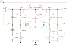
Let's just look at the common input of an A1 not in terms of ac, but in terms of dc and apply various DC voltage values to it - in the picture the potential (and node) called phi ref.
At 0.8A bias the OS largely switch off for 2A pk output current, unless one consider 70uA residual current
as being still switched on, we can see that switch off occur at 1.6A, wich is exactly 2 x the bias Iq and 10W RMS.
as being still switched on, we can see that switch off occur at 1.6A, wich is exactly 2 x the bias Iq and 10W RMS.
Attachments
Last edited:
Let's not make a big deal out of it:
MC12 (with the original MF-A1, component dimensioning and topology) confirms what is already obvious and evident. Iq is falling! To 50% from Vout equal to 3.9V and to 10% from 5.25V, static. My pencil, paper and calculator method yielded a limit of 5.377V.
If the reference remains “zero volts”, we should now also dynamically correctly determine the “wandering offset”, i.e. the (now no longer!) Iq.
I would not be at all surprised if this “dynamic Iq” is also frequency-dependent.
Ultimately, we want to know when the MF-A1 really leaves the classic definition of A operation and switches to AB through to B or C.
Thank you wahab,
at last ... 🙂
Please also show us the limits that are not yet overriding, so that the “A1 nonsense” is finally cleared up.
thx
and greetings,
HBt.
at last ... 🙂
Please also show us the limits that are not yet overriding, so that the “A1 nonsense” is finally cleared up.
thx
and greetings,
HBt.
(2A)^2 * 8 [V/A] = 32W_peakAt 0.8A bias the OS largely switch off for 2A pk output current, (...)
This corresponds exactly to the metrological reality! And the MF company under Austrian management also states this value in exactly the same way, at least I think so 😉.
But we all want to know, and finally definitively, when the electric heating surface leaves real A mode.
It is class A up to 1.6A pk, that is, (RL x 1.6^2)/2 = 10.24W RMS, with 0.7A Iq that makes barely 8W RMS,
on a 4R load that would make no more than 5W and 4W RMS respectively for 0.8A and 0.7A Iqs, not counting
less than 10 damping factor, not that 18-19 on 8R was already a great number.
on a 4R load that would make no more than 5W and 4W RMS respectively for 0.8A and 0.7A Iqs, not counting
less than 10 damping factor, not that 18-19 on 8R was already a great number.
- Home
- Amplifiers
- Solid State
- 3/4 + 3/4 the strange A1