Sorry for the late answer. Have been travelling.
Thank you for the link. That of course is a different take altogether. Nice work.
Yes, you understood correctly on the amps.
But I do understand your dilemma with the NL8. Only if you made a change to an ASP.3 like setup would that work. In the end you/he will run out of excursion on the woofers first in most cases 😆
Wish you fun with the final stint 👍
Yeah, that appears the case. The xmax of the SLS is 10.9mm, while the RSS265HF is 12.3mm. Not clear whether that's one-way or the whole range, hopefully the former. It can also handle way more power.In the end you/he will run out of excursion on the woofers first in most cases 😆
The SBA 10" is 22mm total xmax; Scan-Speak 10" sub is 25mm; the SEAS L26Y hits 30mm, tho -2dB less sensitive than the SS 26W/4558T00, which seems like a sweet spot: At Solen, CA$460. Pricey but not as bad as $750 for the SEAS. Will have to try them for my main studio speakers when I'm feeling flush.

This seems wrong. RSS265HF-8 is actually rated for 14.3mm xmax, which makes me a bit more optimistic.RSS265HF is 12.3mm
I love these modules. Powerful and so easy to implement.
Can someone advise in how to get a power on indicator (led) to the front panel of the chassi?
Thanx!
/JZ
Can someone advise in how to get a power on indicator (led) to the front panel of the chassi?
Thanx!
/JZ
I did not try and check the max excursion in WinISD, but I would not be surprised if you are still able to reach full excursion on all units with the 2x300w at hand - with low end content in the 20-30Hz range. Given that this is still an OB system.This seems wrong. RSS265HF-8 is actually rated for 14.3mm xmax, which makes me a bit more optimistic.
That is just the nature of the physics - not that it's a problem 🙂
Let me know if I misunderstood your question and it is about a specific Chassis or the approach in general:Can someone advise in how to get a power on indicator (led) to the front panel of the chassi?
If you are using one of the buffer modules anyway - then the quick and dirty approach is simply to duplicate the LED's on the buffer board.
You could of course also just have s simple pwr on indication by using the +/-15V pads to connect to an LED with appropiate series resistor.
Quick head calculation 10-15kOhm could be a starting point.
But for the "lazy" I found this: https://www.digikey.dk/en/resources/conversion-calculators/conversion-calculator-led-series-resistor
If you look up the Pascal S-PRO2 or S-A2 add on board documentation - you will find the description of the identical 26pin board connection, where all interfaces including signal / status outputs are described.
You could also just use a power switch with a built-in light/LED.Can someone advise in how to get a power on indicator (led) to the front panel of the chassi?
@Erica.CHi, George
Long time no contact, I hope everything is going well with you
This amplifier is a universal power supply and it will have two variants: ST version and H/B version.
ST version : 2*250W @ 4/8 ohm,
HB version: 500W for CH1 @4 ohm ,and 150W for CH2 @4ohm;
The interface is the same with FFA001/002.
Thanks,
Eric
Did this ST version get completed, read though the thread and didn't see any more mentions of it? Thanks
Hey man, the ST means stereo or two channel model. That's the regular FFAxxx series. The H/B is the variant where one channel is set for more power than the other and best for a two-way active speaker with the H/B module fitted into the speaker box. The regular stereo boards suitcase mounting and sound bars and such where you don't need to send off a speaker wire to the other speakerDid this ST version get completed, read though the thread and didn't see any more mentions of it? Thanks
@Erica.C
Did this ST version get completed, read though the thread and didn't see any more mentions of it? Thanks
The power rating of this 2*250W was covered by our 2*300W(FFA002V2) module, and we just built one prototype and did not proceed the future development, and that's why we did not publish it in the thread.
And you can try our 2*300W module if this meets your application.
Thanks,
Eric
Hi, does this amp contain some kind of protection circuit against starting without source connected?
I used a phone and a 3.5mm to phono cable for testing the amp and everything went well.
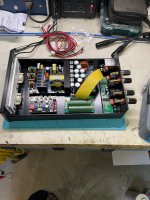
But since I made the chassi for using chassi mounted phono sockets I soldered a wire between the phono sockets signal input and the left solder tag of the PCB mounted phono socket (see attached photo). Then another one between the chassi mounted ground tag and one of the other two solder tags on the PCB.
Lo and behold, the amp didn't make a sound!
I have spent an hour measuring and trying to move wires to no avail.

I am feeling quite stupid and can't figure out what is wrong.
So can anyone explain so I can be social and happy with my kids instead of thinking of wires the entire evening....
I used a phone and a 3.5mm to phono cable for testing the amp and everything went well.
But since I made the chassi for using chassi mounted phono sockets I soldered a wire between the phono sockets signal input and the left solder tag of the PCB mounted phono socket (see attached photo). Then another one between the chassi mounted ground tag and one of the other two solder tags on the PCB.
Lo and behold, the amp didn't make a sound!
I have spent an hour measuring and trying to move wires to no avail.
I am feeling quite stupid and can't figure out what is wrong.
So can anyone explain so I can be social and happy with my kids instead of thinking of wires the entire evening....

Yes, we use the internal short-SW RCA jack in the mono input for better noise immunity.
If you'd like to use the chassis-mounted RCA jack, I would suggest to de-solder the original one in the buffer board.
Thanks,
Eric
If you'd like to use the chassis-mounted RCA jack, I would suggest to de-solder the original one in the buffer board.
Thanks,
Eric
I am skipping the IO-board entirely. Not because of any fault or otherwise, just to save space and since I won't be running it bridged or using the standby switch I might as well skip it and save it in pristine condition for later.
I just ordered a new 26-pin flex cable that I will cut and use to connect signal input and fan.
I just ordered a new 26-pin flex cable that I will cut and use to connect signal input and fan.
kmj.
Keep in mind that the IO board is also providing some gain.
Correction. It seems the gain was removed on newer models. So it should be unity gain now.
Keep in mind that the IO board is also providing some gain.
Correction. It seems the gain was removed on newer models. So it should be unity gain now.
Last edited:
I used XRK’s BTSB input board so I have rca as well as balanced inputs, it also lets you set the gain you want. The little adapter board makes a nice reliable connection to the amp board but takes some space, but the complete amp still ended up fairly compact. By the way the capacitors next to the larger heatsink run surprisingly hot.
Attachments
They do, I think this amp is designed to have a fan for thermal management.By the way the capacitors next to the larger heatsink run surprisingly hot.
There is a socket for a 24V fan on the IO-Board.They do, I think this amp is designed to have a fan for thermal management.
I don't use the IO-board so I connected a 24V 4010 fan to the +12V supply.
Since it run at half the voltage it is more or less soundless.
Last edited:
I'm going passive cooling, outboarding TO-247 mosfets on one and the other I'll will make a negative pressure setup (like a PC) 12V 60mm fans running at 6V... testing is very positive, but I still have to fabricate the enclosures. It went from 70C at heatsinks to ~30C on a 20C environment.There is a socket for a 24V fan on the IO-Board.
I don't use the IO-board so I connected a 24V 4010 fan to the +12V supply.
Since it run at half the voltage it is more or less soundless.
This amps sound fantastic so for me it makes sense to have temps as low as possible (plus is fun)
I did put holes in the bottom and top of the case, I let it run all night. My flir meter showed it at 59 degrees. The opamp used on the input board is a OPA1646 and OPA1637 and they are brighter sounding than what the ones used on the original boards. I have not listened to it on decent speakers if it is a little bright I can dial it back with Ron’s eq function.
- Home
- Vendor's Bazaar
- 2x150W Amp module for sale