Now all mods tested:
- "Cherry" (or OIC) with 2 x 47p and 330p/1R.
- Suckout cap 0.1µ (parallel to R17) removed.
- C11 and C13 changed to 10nF.
Attachments
making da sim reflect 'real life'
Are these all at 20kHz?
And what about 'short_ribbon_osc'? What is the timescale on that?
_______________
I've put in crude inductance for the ribbon cable in my model. But I think the input clean earth on the small PCB is taken to the i/p RCAs and from there, taken directly to Star Earth.
What is the length of this cable from i/p RCA to Star Earth and also the length from small PCB to RCA?
_______________
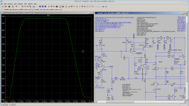
Kean, thiis is a sim of unlimited BW square at outA (before the Zobels etc) Blue curve.
I also show V(inp)-V(inn) magnified by 10x in Red. The voltage across the LTP i/ps is nearly 4V 😱 during the slewing period. It hasn't quite limited so this would be called 'soft slew limiting' but the square wave is definitely non-linear during these periods.
The Green curve is the base current to the VAS input Q6. During the +ve slewing period, the amp has lost control. When the conditions are such that the burst of oscillation extends onto the flat part of the Square, we see the wriggles that Toni shows. During the slewing, the amp is effective 'clipped' so we don't see this nasty stuff.
The sims are 20kHz with only 3n3 load and no 2nd Zobel which is a worst case for the sim. I've got the ribbon inductance in too.
You are right that this is an emphasis on something with should NEVER be triggered by 'real life' signals. In any practical amp, I would use 100kHz BW limitation or even more and all dis evil stuff goes away.
But I've dug a hole and must now try to climb out with people evil pushing me back in. 😡
_____________
Michael & Guru Zan, thank you for kicking a beach bum when he's down 😱
Toni, thanks for helping an old man get up again 🙂
_____________
I must now go and watch over some tastefully clad young ladies and then see how many margaritas I need to flog to buy an old broken PA amp.
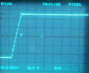
Thanks for this Toni. Can you explain a bit more about the Square Waves? I guess 'short_ribbon_sq1' is at a lower voltage but what about 2, 3 & 4?Here some screen shots using short ribbon cable (2 inch).
Note: distortion increased with short ribbon cable (maybe due to less capacitance):
10 inch ribbon cable0.00187% (bw 80 kHz)2 inch ribbon cable
0.00225% (no bw limit)
0.00250% (bw 80 kHz)
0.00290% (no bw limit)
Are these all at 20kHz?
And what about 'short_ribbon_osc'? What is the timescale on that?
_______________
I've put in crude inductance for the ribbon cable in my model. But I think the input clean earth on the small PCB is taken to the i/p RCAs and from there, taken directly to Star Earth.
What is the length of this cable from i/p RCA to Star Earth and also the length from small PCB to RCA?
_______________
Kean, thiis is a sim of unlimited BW square at outA (before the Zobels etc) Blue curve.
I also show V(inp)-V(inn) magnified by 10x in Red. The voltage across the LTP i/ps is nearly 4V 😱 during the slewing period. It hasn't quite limited so this would be called 'soft slew limiting' but the square wave is definitely non-linear during these periods.
The Green curve is the base current to the VAS input Q6. During the +ve slewing period, the amp has lost control. When the conditions are such that the burst of oscillation extends onto the flat part of the Square, we see the wriggles that Toni shows. During the slewing, the amp is effective 'clipped' so we don't see this nasty stuff.
The sims are 20kHz with only 3n3 load and no 2nd Zobel which is a worst case for the sim. I've got the ribbon inductance in too.
You are right that this is an emphasis on something with should NEVER be triggered by 'real life' signals. In any practical amp, I would use 100kHz BW limitation or even more and all dis evil stuff goes away.
But I've dug a hole and must now try to climb out with people evil pushing me back in. 😡
_____________
Michael & Guru Zan, thank you for kicking a beach bum when he's down 😱
Toni, thanks for helping an old man get up again 🙂
_____________
I must now go and watch over some tastefully clad young ladies and then see how many margaritas I need to flog to buy an old broken PA amp.
Attachments
@ kgrlee
Posting pics of sims is one thing, but posting some nice pics of those "tastefully clad young ladies" would be a welcome break 😀
Posting pics of sims is one thing, but posting some nice pics of those "tastefully clad young ladies" would be a welcome break 😀
Thanks for this Toni. Can you explain a bit more about the Square Waves? I guess 'short_ribbon_sq1' is at a lower voltage but what about 2, 3 & 4?
Are these all at 20kHz?
And what about 'short_ribbon_osc'? What is the timescale on that?
All square wave pictures where 20kHz also the high resolution ones with 1µs/div.
Short_ribbon_sq1 - 4 are increasing level of same square wave frequency.
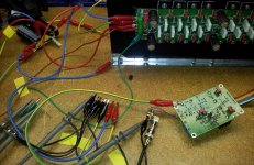
Input/RCA cable is about 3 inch to pcb input socket.I've put in crude inductance for the ribbon cable in my model. But I think the input clean earth on the small PCB is taken to the i/p RCAs and from there, taken directly to Star Earth.
What is the length of this cable from i/p RCA to Star Earth and also the length from small PCB to RCA?
Thick cable from amp ground to star ground 50 cm.
Thick cable from input pcb to star ground 50 cm.
The lengths reflect nearly a "real life" wiring in an amplifier case.
You're welcome!Toni, thanks for helping an old man get up again 🙂
Attachments
Guru Zan ...kick... a beach bum when he's down
To dispel a falsehood is not to kick a man but to free him from error.
Search only for the truth and do not hold on to beliefs from pride.
This is called "Free yourself of attachment to illusion".
It is the path of wisdom.
The book of venerated master Bode is so deep that even a tiny fraction is powerful.
All credit to him for any correctness that this humble novice may have shown.😉
Also my thanks to Toni too for his excellent work.
Best wishes
David
Last edited:
more 'pure Cherry' mods
In the meantime ..
_______________
Toni, if you haven't dismantled the Cherry version could you try another 2 dodges please.
The ribbon is a short & misterminated line so is probably better simmed with both Inductance & capacitance. There's a lot of capacitance on the ribbon lines so my crude sim for this is probably OK.
But Lp4, the Clean earth connection to Star Point via the RCAs, may be a wonky sim
__________________
There are several methods available but some introduce quite a lot of distortion by compromising the Holy HiZ VAS output. The above mods attempt to do it without the evils of TMC etc and hence retain the benefits of 'pure Cherry' 😀
_______________
May I join Guru Zan in thanking Toni for his work and particularly for humouring a senile old man's ravings. 😱
This Grasshopper thanks Guru Zan for any kicks administered for purely educational purposes 🙂To dispel a falsehood is not to kick a man but to free him from error.
Search only for the truth and do not hold on to beliefs from pride.
This is called "Free yourself of attachment to illusion".
It is the path of wisdom.
The book of venerated master Bode is so deep that even a tiny fraction is powerful.
All credit to him for any correctness that this humble novice may have shown.😉
In the meantime ..
_______________
Toni, if you haven't dismantled the Cherry version could you try another 2 dodges please.
- the Cherry capacitor C1 becomes 47p + 100R in series.
- (C10, the capacitor to the other side of the current mirror should follow but this isn't strictly necessary just to check stability.)
- If this shows an improvement, a 10p capacitor on the base of the VAS input (Q6 base) to the rail may improve things further.
- Lp4 100nH to model the connection of Clean earth on the small PCB to the Star point via RCAs.
- Lp1, 2, 3, 5, 7 & 9 to model the ribbon cable. Both these are crude but better than nothing.
- the Cherry cap+resistor and the matching network to the other side of the CM as above.
- The 10p on the input of the VAS
- R22 becomes 27R
- and is decoupled with 330p+1R
- C16 across R17 33R is removed
- C11 & C13 at the bias transistor become 10n
- Q6 collector is now taken to the Dirty ground on the small PCB
- C3/4 100n to Clean ground on the small PCB are replaced by a single C17 1u from rail to rail
- On my .ASC, I've had to take D15, the cascode Zener to Dirty ground on the small PCB else it won't run. (You have it to Clean earth)
The ribbon is a short & misterminated line so is probably better simmed with both Inductance & capacitance. There's a lot of capacitance on the ribbon lines so my crude sim for this is probably OK.
But Lp4, the Clean earth connection to Star Point via the RCAs, may be a wonky sim
__________________
That should be the IPS has lost control. The Inner Cherry Loop obviously needs to be stabilised further so it is well behaved when not mastered by the IPS.During the +ve slewing period, the amp has lost control.
There are several methods available but some introduce quite a lot of distortion by compromising the Holy HiZ VAS output. The above mods attempt to do it without the evils of TMC etc and hence retain the benefits of 'pure Cherry' 😀
_______________
May I join Guru Zan in thanking Toni for his work and particularly for humouring a senile old man's ravings. 😱
Attachments
[*]the Cherry capacitor C1 becomes 47p + 100R in series.
I assume you have looked at the return ratio around the OPS as C1 is altered?
It does not do what I expected.
Nor when a series resistor is added.
Low frequency behaves as expected, there is a frequency where the return ratio is practically unaffected, above that it seems to move in opposition.
Perhaps I miss some simple point but I need to understand that.
If you haven't done so then check it out.
If you have then do you have an explanation?
Best wishes
David
Ribbon Cable
I'm wondering if, computer Ultra DMA/Ultra ATA IDE Ribbon Cable could be advantagous ?
I'm not suggesting that ALL 80 wires are used 😀 only what's required plus the corresponding ground wires 😉
I'm wondering if, computer Ultra DMA/Ultra ATA IDE Ribbon Cable could be advantagous ?
ATA's cables have had 40 wires for most of its history (44 conductors for the smaller form-factor version used for 2.5" drives—the extra four for power), but an 80-wire version appeared with the introduction of the Ultra DMA/33 (UDMA) mode. All of the additional wires in the new cable are ground wires, interleaved with the previously defined wires to reduce the effects of capacitive coupling between neighboring signal wires, reducing crosstalk.
https://en.wikipedia.org/wiki/Parallel_ATA
I'm not suggesting that ALL 80 wires are used 😀 only what's required plus the corresponding ground wires 😉
I'm wondering if, computer Ultra DMA/Ultra ATA IDE Ribbon Cable could be advantagous ?
I'm not suggesting that ALL 80 wires are used 😀 only what's required plus the corresponding ground wires 😉
I'm sure the amplifier will work with high performance if you design the pcb to hold 80 pin sockets ... 🙂
But advantagous?
Currently measured: 2 parallel wires of the used 10 inch ribbon cable have about 14pF and a wire embedded between 2 wires (powergnd) have about 28pF capacitance. If you add capacitors with value 28pF on BIASH<=>pwrgnd and BIASL<=>pwrgnd you will get 3 degree better (!) phase margin => I think this explains, why the long ribbon cable helps to stabilize the amplifier.The addition of the 'Ribbon' inductances changes many things and I'll have to work out how to do the THD Analyzer properly.
The ribbon is a short & misterminated line so is probably better simmed with both Inductance & capacitance. There's a lot of capacitance on the ribbon lines so my crude sim for this is probably OK.
IMHO for high frequency the inductance of the ribbon cable is even in a bad terminated bus cable not so important as the inter cable capacitance.
You are welcome too!May I join Guru Zan in thanking Toni for his work and particularly for humouring a senile old man's ravings. 😱
Last edited:
Originally Posted by astx
I'm sure the amplifier will work with high performance if you design the pcb to hold 80 pin sockets .
I wasn't expecting Anyone to use ALL 80, as i stated !
Instead, cut the cable into the exact number required, & of course, don't use the connectors 😉
Cherry & sims
Increasing C1, the Cherry cap, reduces the Main Loop Gain. In that respect, it behaves like simple amps with plain Miller. But increasing C1 increases the Loop Gain of the Inner Cherry Loop cos it is extra feedback around this.
Please bear in mind that this already goes beyond Prof. Cherry's recommendations as I point out in #512 of this thread. We have 4 devices, enhanced VAS + EF2 in a feedback loop so 4 x 20dB/8ve final roll-off, which is only brought down to 3 x 20dB/8ve by the Cherry cap. This can be tweaked stable (VAS emitter resistor + its judicious decoupling) for specific cases but only up to a point. Stray capacitances, parasitic inductances & wonky loads may be too much.
I've had some 'real life' success bending Cherry's rules but this required my own rules.
For the 50W 8R amp(s) (production & experimental versions) and one 100W 8R amp, this is having EVERYTHING including the outputs in a 2x3" single sided through hole PCB. Hence the sim (my own linear circuit analyzer) was probably closer to real life than what we are playing with now.
I've never played with an amp as big as Toni's but I do want to build such a beast as I had such an amp for personal use for a long time.
To complicate matters, this 'instability' in Toni's Cherry version isn't 'linear'. It appears at high levels when the amp is slew limiting. [deleted: major rant about allowing amps to slew limit and why you need 100kHz i/p BW limitation]
I'm in an unenviable position of trying to trouble shoot something at long distance using tools which I KNOW are wonky ,. ie the SPICE doesn't reflect real life. 😡
My best clue is that the 'Baxandall pair' VAS sim I was playing with shows almost exactly the behaviour that Toni measures.
At present, I'm scratching around for stuff which might possible indicate this. The base current of the VAS i/p Q6 I showed in #522 is the wildest happening when I can simulate the stuff Toni sees. (with the 'Baxandall pair' version).
Changing the Cherry cap from 47p to 47p+100R 'damps' this and has a small effect on LG which is better seen on Nyquist. It has only small effect on the traditional 'linear' PM & GM. Similarly the 10p on the input of the VAS which I haven't checked out in detail.
... and I'm doing all this with the 2nd Zobel disabled and around 1-3nF pure capacitive load cos this seems to provoke the most instability.
Incidentally, using my Lp inductors to sim the Ribbon etc has produced some really weird Nyquist plots.
__________________
FWIW, my sims show that BIASH, BIASL and the power lines are relatively uncritical for inductance. The power lines have good damping from the 10R resistors. Not sure about the feedback OutA line.
However, my Lp2 between the Dirty small PCB earth (pga on my .ASC) and PWRGND (pwg on my .ASC) and also Lp4 between Clean earth (only on the small PCB) and Star point are critical.
I'm pretty certain my crude simulation of these is wonky and would appreciate any advice. With this in place, LTspice doesn't like D15, the Z12 Zener decoupled to Clean earth so I've taken it to Dirty earth.
__________________
Toni, can you confirm the replacement of C1/3 100n to Clean earth on the small PCB with the single C17 100n across the rails?
Also the earthing of D15, the 12V Zener and the collector of Q6.
__________________
A reminder that some other distortion mechanism is limiting what THD Toni measures to 10dB more than sims of either the TMC or Cherry version. This is likely layout, decoupling & earthing.
Firstly, I gotta say I prefer to look at the Inner Cherry Loop at the i/p of the VAS rather than the OPS like Toni. I'm still trying to get my head around what Toni reports as PM & GM.I assume you have looked at the return ratio around the OPS as C1 is altered?
It does not do what I expected.
Nor when a series resistor is added.
Low frequency behaves as expected, there is a frequency where the return ratio is practically unaffected, above that it seems to move in opposition.
Increasing C1, the Cherry cap, reduces the Main Loop Gain. In that respect, it behaves like simple amps with plain Miller. But increasing C1 increases the Loop Gain of the Inner Cherry Loop cos it is extra feedback around this.
Please bear in mind that this already goes beyond Prof. Cherry's recommendations as I point out in #512 of this thread. We have 4 devices, enhanced VAS + EF2 in a feedback loop so 4 x 20dB/8ve final roll-off, which is only brought down to 3 x 20dB/8ve by the Cherry cap. This can be tweaked stable (VAS emitter resistor + its judicious decoupling) for specific cases but only up to a point. Stray capacitances, parasitic inductances & wonky loads may be too much.
I've had some 'real life' success bending Cherry's rules but this required my own rules.
For the 50W 8R amp(s) (production & experimental versions) and one 100W 8R amp, this is having EVERYTHING including the outputs in a 2x3" single sided through hole PCB. Hence the sim (my own linear circuit analyzer) was probably closer to real life than what we are playing with now.
I've never played with an amp as big as Toni's but I do want to build such a beast as I had such an amp for personal use for a long time.
To complicate matters, this 'instability' in Toni's Cherry version isn't 'linear'. It appears at high levels when the amp is slew limiting. [deleted: major rant about allowing amps to slew limit and why you need 100kHz i/p BW limitation]
I'm in an unenviable position of trying to trouble shoot something at long distance using tools which I KNOW are wonky ,. ie the SPICE doesn't reflect real life. 😡
My best clue is that the 'Baxandall pair' VAS sim I was playing with shows almost exactly the behaviour that Toni measures.
At present, I'm scratching around for stuff which might possible indicate this. The base current of the VAS i/p Q6 I showed in #522 is the wildest happening when I can simulate the stuff Toni sees. (with the 'Baxandall pair' version).
Changing the Cherry cap from 47p to 47p+100R 'damps' this and has a small effect on LG which is better seen on Nyquist. It has only small effect on the traditional 'linear' PM & GM. Similarly the 10p on the input of the VAS which I haven't checked out in detail.
... and I'm doing all this with the 2nd Zobel disabled and around 1-3nF pure capacitive load cos this seems to provoke the most instability.
Incidentally, using my Lp inductors to sim the Ribbon etc has produced some really weird Nyquist plots.
__________________
Toni already does this on his ribbon. You can see this on his early pics & PCB layouts. That's why my ribbon sim is numbered LP1, 3, 5, 7 & 9 with the earth between Dirty ground & PwrGnd Lp2, shown as 1/5 the inductance of the others.All of the additional wires in the new cable are ground wires, interleaved with the previously defined wires to reduce the effects of capacitive coupling between neighboring signal wires,
Thanks for this Toni. I think for the BIASH & BIASL lines, there is already so much capacitance due to the drivers etc that this makes little difference. I might be wrong so I'll insert these evil capacitances in my sim.astx said:Currently measured: 2 parallel wires of the used 10 inch ribbon cable have about 14pF and a wire embedded between 2 wires (powergnd) have about 28pF capacitance. If you add capacitors with value 28pF on BIASH<=>pwrgnd and BIASL<=>pwrgnd you will get 3 degree better (!) phase margin => I think this explains, why the long ribbon cable helps to stabilize the amplifier.
IMHO for high frequency the inductance of the ribbon cable is even in a bad terminated bus cable not so important as the inter cable capacitance.
FWIW, my sims show that BIASH, BIASL and the power lines are relatively uncritical for inductance. The power lines have good damping from the 10R resistors. Not sure about the feedback OutA line.
However, my Lp2 between the Dirty small PCB earth (pga on my .ASC) and PWRGND (pwg on my .ASC) and also Lp4 between Clean earth (only on the small PCB) and Star point are critical.
I'm pretty certain my crude simulation of these is wonky and would appreciate any advice. With this in place, LTspice doesn't like D15, the Z12 Zener decoupled to Clean earth so I've taken it to Dirty earth.
__________________
Toni, can you confirm the replacement of C1/3 100n to Clean earth on the small PCB with the single C17 100n across the rails?
Also the earthing of D15, the 12V Zener and the collector of Q6.
__________________
A reminder that some other distortion mechanism is limiting what THD Toni measures to 10dB more than sims of either the TMC or Cherry version. This is likely layout, decoupling & earthing.
Last edited:
Originally Posted by kgrlee
Toni already does this on his ribbon.
Thanks, i wonder why he didn't mention it in his reply ?
Re - Dirty Conections
I mentioned previously, that it's preferable to route Low/Med/High returns seperately to a Star Ground Point.. In fact, it's even better to route EACH individual return seperatly to the SGP. A guy called Dennis Moorcroft of DNM in the UK pioneered this in the early 80's with his audio gear.
Like all DNM electronics since 1982, the 3C makes extensive use of star earthing in order to ensure that every point in the amplifier has its own dedicated earth reference - rather than the more conventional bus-bar system used by many manufacturers.
DNM Products - Previous DNM Preamplifiers
Firstly, I gotta say I prefer to look at the Inner Cherry Loop at the i/p of the VAS rather than the OPS like Toni.
It makes practically no difference.
Increasing C1, the Cherry cap, reduces the Main Loop Gain. In that respect, it behaves like simple amps with plain Miller. But increasing C1 increases the Loop Gain of the Inner Cherry Loop cos it is extra feedback around this.
The net result is that the return ratio around the OPS hardly varies at all.
I am still not sure exactly why it varies in the way it does but it makes little difference.
An increase in the VAS emitter resistor by-pass capacitor looks like it will improve your "Cherry" stability.
Haven't tested this fully, just an initial inspection, but try around 820pF.
The sims I ran to try this have further convinced me that you won't be able to match a properly optimised Bode maximum feedback network.
I now see why Mike used shunt compensation but still think it will be possible to do better.
I also start to understand why really fast amplifiers like oscilloscope verticals use a few careful inductors.
What do you think of a few small air cored toroids in the compensation or input filter?
Probably more comments on your post after I think a bit.
Very educational thread, so thanks to you too.
Best wishes
David
.
Last edited:
However, my Lp2 between the Dirty small PCB earth (pga on my .ASC) and PWRGND (pwg on my .ASC) and also Lp4 between Clean earth (only on the small PCB) and Star point are critical.
IMHO including the inductances doesn't help you to find better PM. It only confuses LTSpice. Think of an older posting from me where I compared long/short ribbon cable against THD. So try to sim with caps with 2 x 28p from BIASL/BIASH connected to pwrground and another time with 2 x 6p connected to pwrground. I think the THD difference using short or long ribbon cable is based mainly on this extra VAS load.
Note: The input capacitance of the used driver transistors is low and the extra load of 2x22p on VAS is not negligible.
Toni, can you confirm the replacement of C1/3 100n to Clean earth on the small PCB with the single C17 100n across the rails?
Also the earthing of D15, the 12V Zener and the collector of Q6.
- 2 x 100n and 2 x 470µ from rails to powergnd are cleaning the supply for Input/VAS stage.
- Collector of VAS predriver Q6 has moved from clean ground to pwrground
- D15/12V Zener for cascode is connected already on clean ground
Those versed in the art will have gathered that 'pure Cherry' is really an exercise in keeping the Holy HiZ VAS output clear of Michael's (and anyone else's) evil shunt or feedback bits. Its DEFINITELY possible to do better than their evil methods 😀The sims I ran to try this have further convinced me that you won't be able to match a properly optimised Bode maximum feedback network.
I now see why Mike used shunt compensation but still think it will be possible to do better.
Dave, I'll be interested to see your implementation of Bode's mythical 'max fb network'. I've my own version of this from my misguided TPC days. 🙂
_______________
Toni, at present, I'm not trying to find better PM.IMHO including the inductances doesn't help you to find better PM. It only confuses LTSpice. Think of an older posting from me where I compared long/short ribbon cable against THD. So try to sim with caps with 2 x 28p from BIASL/BIASH connected to pwrground and another time with 2 x 6p connected to pwrground. I think the THD difference using short or long ribbon cable is based mainly on this extra VAS load.
Note: The input capacitance of the used driver transistors is low and the extra load of 2x22p on VAS is not negligible.
I'm trying to make SPICE replicate your 'real life' results. That's always the first move if you want useful results from SPICE.
The bits I recommend along the way are just incidental cos evil people are chipping away at my (pseudo) guru disguise. 😱
___________________
When SPICE is confused, you usually have a problem. eg taking Q6, the VAS input, collector to Clean earth (with the inductors) makes SPICE go haywire. I KNOW this will cause problems. Luckily your 'real life' example only sees a small increase in THD.
___________________
Please confirm C3/4 the 100n on the ips rails are now taken to powergnd and not Clean earth.
- 2 x 100n and 2 x 470µ from rails to powergnd are cleaning the supply for Input/VAS stage.
DEFINITELY a good move, in SPICE ... and more importantly, in 'real life'
- Collector of VAS predriver Q6 has moved from clean ground to pwrground
____________
Toni, DON'T try my recommendations from #526 yet. There's a better solution.
I've been blind and looking at dem traditional 'linear' measures like PM, GM & Nyquist when there are much better 21st century tools staring me in the face. I'll blame the evil pseudo gurus for misleading me 🙄
The 'real' problem was also staring me in the face cos I posted it in #522 without looking at it properly.
More after I come back from looking after my tastefully clad young ladies 🙂
Improvements in compensation
Hi Toni.
I may have another improvement for your TMC version.
TMC is the best of the variants tested so far I think?
I am not up to date with the exact latest winner so the improvement is not fully checked but try capacitor about 820 pF in parallel with the VAS emitter resistor ( a decouple capacitor). This works for TMC similarly to its use in the "Cherry" version.
It should improve the GM without much other effect.
It seems to help with an RHP zero that should be checked and totally eliminated.
Best wishes
David
You are right. GM betters about 2-3dB using the cap. Will test this too.
... betters about 2-3dB using the cap. Will test this too.
Nice to confirm it works for you.
A little extra stability is nice when it is practically free but also excellent that it reveals the RHP anomaly that is a hidden non optimisation.
The power of Bode theory to drive practical improvements.😉
Best wishes
David
Unfair! Using my Holy methods on evil TMC 😡I may have another improvement for your TMC version.
.. but try capacitor about 820 pF in parallel with the VAS emitter resistor ( a decouple capacitor). This works for TMC similarly to its use in the "Cherry" version.
OK, I confess. This is probably useful in any amp with a VAS emitter resistor. [deleted: 3 page rebuttal of MikeK's probable comments on the topic]
______________________
Toni, if you haven't already written me off as a fraud ... Can you try the Cherry version as follows.
- C1 & 10 revert to simple 47p
- R22 is 27R as previous Cherry versions
- which is decoupled with C7 330p in series with R27 1R
- remove C16 across R17 the 33R at the base of the outputs
- C11/13 at the bias transistor become 10n
- the change from previous Cherry versions is 10R in series with the VAS input, Q6's emitter
_______________________
Toni, I still can't get my sim to replicate the faults you show in #518. I'm simulating your ribbon cable capacitance with Cp1-4. It doesn't show more THD with 2" compared to 10". About the only thing it seems to show is the evils of taking Q6 collector to Clean earth.
But can you confirm that C1/3 100n at the ips rails are now taken to Dirty earth on the small PCB. It was taken to Clean on your early PCBs.
Or is there a difference between your #457 latest TMC version and the Cherry version you are testing?
_______________________
But I think I'm getting enough to do something about the oscillation you see.
The good news is that the THD analyzer seems only slightly affected.
Attachments
Last edited:
- Home
- Amplifiers
- Solid State
- 2stageEF high performance class AB power amp / 200W8R / 400W4R