hello ZM,
can we calculate C3 using this formula:
C = 1/(2*pi*R*f)
R = output impedance
f = lowest frequency to amplify
thanks.
can we calculate C3 using this formula:
C = 1/(2*pi*R*f)
R = output impedance
f = lowest frequency to amplify
thanks.
you mean C3 - output cap in Mu stage , on top?
yes, for R use R of load - speaker
So for 20hz is
C = 1 / (2*3.14*8*20) = 0.000995F or 995uf > 1000uf
why do we use 10000uf instead of 1000uf ?
and about voltage rating, why using 75v minimum specs
wasn't there only 28v at the drain point through the output capacitor?
sorry for the boring school questions 😅
thanks.
think phase
why not shooting at 2Hz , so you have clean 10 or 15 or 20
not to mention 4R speakers .......... and jumping (both up and down) impedance, possibly
regarding cap voltage - swing is , ideally , rail to gnd
so?

why not shooting at 2Hz , so you have clean 10 or 15 or 20
not to mention 4R speakers .......... and jumping (both up and down) impedance, possibly
regarding cap voltage - swing is , ideally , rail to gnd
so?
i see....
so for 2hz and 4RL
C = 1 / (2*3.14*4*2) = 0.01990F or 19,900uf > 20,000uf
and for voltage rail to gnd is 60v that's why 75v caps is minimum.
ok i got it.
what about the current through C3,
do we need high current big can capacitor?
so for 2hz and 4RL
C = 1 / (2*3.14*4*2) = 0.01990F or 19,900uf > 20,000uf
and for voltage rail to gnd is 60v that's why 75v caps is minimum.
ok i got it.
what about the current through C3,
do we need high current big can capacitor?
10m is enough , this still isn't magnetizing machine 🙂
you need proper cap , current to speaker is going through
you need proper cap , current to speaker is going through
lousy late night pics
lazy to arrange proper light
missing some tiny parts - few caps and small Graetzs, need to order them tomorrow ....
so , testing in few days ......
Mu lives!
tried all sorts of maltreatment ...... and no poof!
trimpot functioning pretty well for Iq adjust ; with preset of 10K from rail to gate , Iq was 3A3 , trimmed to 3A@30V
Ugs is 4V66
tomorrow testing of SIT gain pcb (SIT in situ
 ) , then together
 first Papa's 2SK77B , then THF51
after that Mos Schade gain pcb
..first Papa's 2SK77B , then THF51
after that Mos Schade gain pcb
Excellent Zen Mod play fun with audio game


Hi Zen Mod, looking forward to your test results.
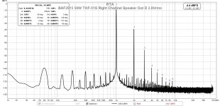
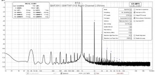
I did some harmonic distortion measurements on my THF-51S amps recently and I was surprised by the results. I measured the distortion with the speaker output at positions A, B, C, and D, and the results were opposite to what I expected. The distortion was the lowest at position A, at the THF-51S drain, and highest at position D.
The measured distortions are on the high side, although that may be the product of my equipment, comprising a Victor 1kHz oscillator, resistor based voltage divider from Akitika schematic, Focusrite Scarlett 2i2 Gen 2, and REW software.
I double checked my circuit board and did not find any errors in wiring. The results were the same for both mono blocks, except the distortion was higher for the right channel amp.
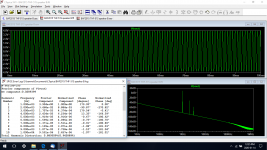
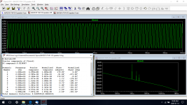
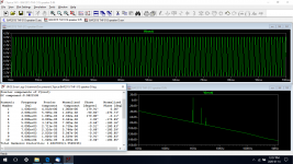
I was curious enough that although I had never used LTspice before, I learned enough to input the circuit and run the simulation. I substituted similar models for some of the components, as I could not find exact models for 4N37, IXFN140N20P, and THF-51S. The substitutions were 4N28, IXFN120N20, and 2SK180 respectively. The results for the simulation were in the same ballpark as my measurements, although the simulation produced lower levels of distortion. The simulations' harmonic distortions were also lowest for speaker output position A and highest for speaker position D.
So I am puzzled. Nelson had explained in his BAF2015 video that position A should have the highest distortion and position D the lowest.
Perhaps there is an error or errors in my build that I am not seeing, or my layout of the components adversely affected the circuit, and maybe there are errors in my simulations, as I had never simulated a circuit before, or errors in my distortion measurements. I had measured the distortion of my 1kHz test signal before and its distortion level was quite low so I know that the test signal is not an issue.
The amps do sound good though.
Here are some of my measured distortions (8R load) and simulations:
I did some harmonic distortion measurements on my THF-51S amps recently and I was surprised by the results. I measured the distortion with the speaker output at positions A, B, C, and D, and the results were opposite to what I expected. The distortion was the lowest at position A, at the THF-51S drain, and highest at position D.
The measured distortions are on the high side, although that may be the product of my equipment, comprising a Victor 1kHz oscillator, resistor based voltage divider from Akitika schematic, Focusrite Scarlett 2i2 Gen 2, and REW software.
I double checked my circuit board and did not find any errors in wiring. The results were the same for both mono blocks, except the distortion was higher for the right channel amp.
I was curious enough that although I had never used LTspice before, I learned enough to input the circuit and run the simulation. I substituted similar models for some of the components, as I could not find exact models for 4N37, IXFN140N20P, and THF-51S. The substitutions were 4N28, IXFN120N20, and 2SK180 respectively. The results for the simulation were in the same ballpark as my measurements, although the simulation produced lower levels of distortion. The simulations' harmonic distortions were also lowest for speaker output position A and highest for speaker position D.
So I am puzzled. Nelson had explained in his BAF2015 video that position A should have the highest distortion and position D the lowest.
Perhaps there is an error or errors in my build that I am not seeing, or my layout of the components adversely affected the circuit, and maybe there are errors in my simulations, as I had never simulated a circuit before, or errors in my distortion measurements. I had measured the distortion of my 1kHz test signal before and its distortion level was quite low so I know that the test signal is not an issue.
The amps do sound good though.
Here are some of my measured distortions (8R load) and simulations:
Attachments
-
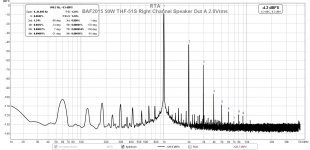 BAF2015 50W THF-51S Right Channel Speaker Out A 2.8Vrms.jpg187.5 KB · Views: 362
 -
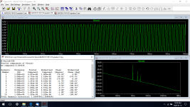 BAF2015 50W THF-51S C out FFT LTspice 1W.png99.3 KB · Views: 120
 -
 BAF2015 50W THF-51S C out LTspice 1W.png55.1 KB · Views: 133
 -
 BAF2015 50W THF-51S B out FFT LTspice 1W.png96.3 KB · Views: 133
 -
 BAF2015 50W THF-51S B out LTspice 1W.png56.7 KB · Views: 127
 -
 BAF2015 50W THF-51S A out FFT LTspice 1W.png109.4 KB · Views: 150
 -
 BAF2015 50W THF-51S A out LTspice 1W.png58.1 KB · Views: 354
 -
 BAF2015 50W THF-51S Right Channel Speaker Out D 2.8Vrms.jpg188.8 KB · Views: 344
 -
 BAF2015 50W THF-51S Right Channel Speaker Out C 2.8Vrms.jpg217.1 KB · Views: 348
 -
 BAF2015 50W THF-51S Right Channel Speaker Out B 2.8Vrms.jpg214.3 KB · Views: 348
Pa is (almost exclusively) unmistakable when schematics are in question , but here and there mistake or two can slip in , when he's explaining and numbering some things
nothing but good thing , to keep us Greedy Boyz awake 🙂
however , I believe he's (mostly) right saying that THD goes down , more you put Mu to work ..... but remember that he was talking about 2SK77B in lower position , , or mos puck ( for Schade poor greedy bztrd iteration)
to cover all things , one need to fiddle with output node voltage potential , to fine tune and squeeze last ounce of performance ...... which means - for each output node position ( be it higher or lower in Mu , or all down , so no Mu.just simple CCS action) , you need to fine tune voltage potential across SIT
anyway , once when you close , you're close ....... just leave it powered and put some music ........ 🙂
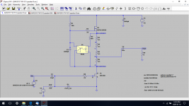
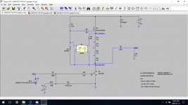
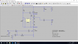
here it is , for your LTSpice amusement , so you can play with ....... try moving output node in this sim , you'll be surprised
I'll comment more , in a day or two , after my own measurements in dedicated thread about Singing Bush
hopefully
nothing but good thing , to keep us Greedy Boyz awake 🙂
however , I believe he's (mostly) right saying that THD goes down , more you put Mu to work ..... but remember that he was talking about 2SK77B in lower position , , or mos puck ( for Schade poor greedy bztrd iteration)
to cover all things , one need to fiddle with output node voltage potential , to fine tune and squeeze last ounce of performance ...... which means - for each output node position ( be it higher or lower in Mu , or all down , so no Mu.just simple CCS action) , you need to fine tune voltage potential across SIT
anyway , once when you close , you're close ....... just leave it powered and put some music ........ 🙂
here it is , for your LTSpice amusement , so you can play with ....... try moving output node in this sim , you'll be surprised
I'll comment more , in a day or two , after my own measurements in dedicated thread about Singing Bush
hopefully
Attachments
Hi Zen Mod,
I am enjoying the music, and my measurements do not change my high opinion of the design.
Thanks for the file, I'll have a go at it.
I am enjoying the music, and my measurements do not change my high opinion of the design.
Thanks for the file, I'll have a go at it.
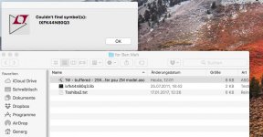
o.k. I took the NMos symbol instead,
more problems...
- green LED is special ZM and not included
- in my toshiba2.txt is only the 8mA model included, either people must delete
in the Toshiba2.txt the added 8mA or one must add the ...8ma to the name in the Spice model like this
J2sk1708mA.
:--))
more problems...
- green LED is special ZM and not included
- in my toshiba2.txt is only the 8mA model included, either people must delete
in the Toshiba2.txt the added 8mA or one must add the ...8ma to the name in the Spice model like this
J2sk1708mA.
:--))
Focusrite Scarlett 2i2 Gen 2, and REW software
Are you sure you are not at the limit of overdriving your 2i2 input? I'm currently learning myself how to do distortion measurements and tried first to measure distortion of the 2i2 in closed loop and can achieve about 0.007% THD.
- Home
- Amplifiers
- Pass Labs
- 2sk77b