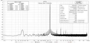
I used a voltage divider attenuator circuit to lower the voltage to the 2i2, so no overload:
https://www.akitika.com/documents/BuildingTheAttenuatorRev4.pdf
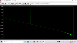
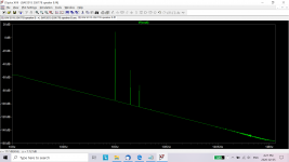
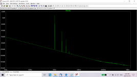
Here is my measurement of my 1k oscillator:
https://www.akitika.com/documents/BuildingTheAttenuatorRev4.pdf
Here is my measurement of my 1k oscillator:
Attachments
I am pretty sure you are getting those results because of a fault in your speakers Ben.
Fortunately for you I am the only one who can fix this so please ship them to me for long term treatment and I'll get them back to you once they are (eventually) cured of this reverse distortion phenomenon.
Interesting to see that 3H is higher than 2H? Isn't this supposed to be 2H dominant?
Fortunately for you I am the only one who can fix this so please ship them to me for long term treatment and I'll get them back to you once they are (eventually) cured of this reverse distortion phenomenon.
Interesting to see that 3H is higher than 2H? Isn't this supposed to be 2H dominant?
How could I have missed that? I forgot to connect the speakers.🙂
The last shot is of the oscillator only. The distortion measurements for the amp is in post #193 - lots of second order harmonic.
The last shot is of the oscillator only. The distortion measurements for the amp is in post #193 - lots of second order harmonic.
So I am puzzled. Nelson had explained in his BAF2015 video that position A should have the highest distortion and position D the lowest.
Every part has its own sweet spot. The 2SK77 THF51S and 2SK182 are
all different parts, so some experimentation is in order to find the spot.
It sounds sweet as-is. I am enjoying the sound immensely. I was just curious so I started poking around.
Thank you for giving us these circuit designs.
Thank you for giving us these circuit designs.
Singing Bush cooking
pics little later

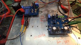
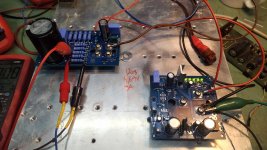
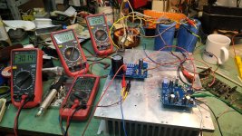
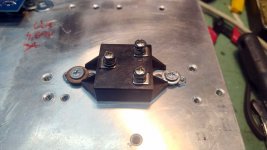
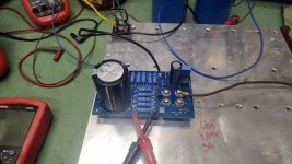
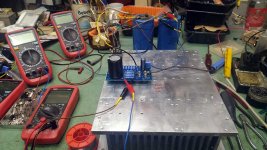
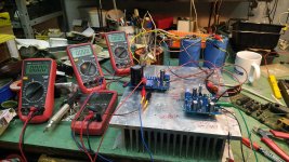
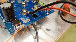
so , it's cooked ; 2SK77B as gain module
behaving impeccable in DC domain ; rail 61Vdc , Iq 3A
at startup , output node lazy jumps to 17V (SIT conducting and fully open while mos puck still closed), then hesitates , then nicely slowly rising (mos puck starting and finally fully conducting) to 31Vdc , where is set
powering off - almost instant drain of PSU caps ( had 66mF on bench)
nice and stable ; due to regulated biasing voltage , usual test span of 10% +/- change of rail resulting in no change of output node voltage
will put THF51 instead- tomorrow and try it in DC realm , and maybe even AC battery of tests
Attachments
-
 IMG_20200205_181550.jpg119.9 KB · Views: 148
 -
 IMG_20200205_181532.jpg110.3 KB · Views: 135
 -
 IMG_20200205_175934.jpg102.3 KB · Views: 123
 -
 IMG_20200205_175756.jpg103.9 KB · Views: 133
 -
 IMG_20200205_175751.jpg126.3 KB · Views: 154
 -
 IMG_20200205_145906.jpg86.9 KB · Views: 299
 -
 IMG_20200205_145530.jpg52.6 KB · Views: 339
 -
 IMG_20200205_143312.jpg74.7 KB · Views: 339
 -
 IMG_20200205_142904.jpg70.4 KB · Views: 343
 -
 IMG_20200205_142859.jpg112.2 KB · Views: 349
Last edited:

😎😎😎😎
😀😀😀😀😀😀😀
poster this!!!
🙂
(imagine Chicken ZM , fiddling with half grand transistor , without protection ? ........ no Bubba .........
)Attachments

Hi Zen Mod,
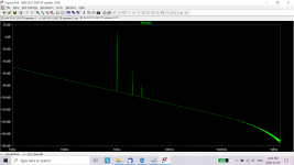
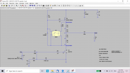
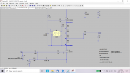
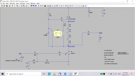
I couldn't get your LTSpice file to run - my LTSpice library does not have all of the component models. So I took the 2SK77B from your file and put it into my simulation circuit and ran it (1W output).
With the 2SK77B in place of the Tokin, the harmonic distortion is now highest at speaker location A. So all is good. Now I know that all SITs are not equal.
There seemed to be an anomaly in my simulation though as speaker position C gave the lowest distortion. But it's only a simulation - could be component model inaccuracies, or something else.
Unfortunately I don't have any 2SK77Bs to test the real thing. Lucky you!!😀
Attachments
-
 BAF2015 2SK77B Speaker D LTSpice fft.png123.6 KB · Views: 121
 -
 BAF2015 2SK77B Speaker D LTSpice.png136.2 KB · Views: 133
 -
 BAF2015 2SK77B Speaker C LTSpice fft.png122.4 KB · Views: 125
 -
 BAF2015 2SK77B Speaker C LTSpice.png136.3 KB · Views: 144
 -
 BAF2015 2SK77B Speaker B LTSpice fft.png122.4 KB · Views: 341
 -
 BAF2015 2SK77B Speaker B LTSpice.png137.9 KB · Views: 347
 -
 BAF2015 2SK77B Speaker A LTSpice fft.png122.3 KB · Views: 351
 -
 BAF2015 2SK77B Speaker A LTSpice.png131 KB · Views: 354
Last edited:
poster this!!!
🙂
(imagine Chicken ZM , fiddling with half grand transistor , without protection ? ........ no Bubba .........
How you like it vs ths51?
answer on that will wait few months , to compare amps in auditory way, side to side
obligated to make my own , and THF iteration for my Polish guy ....... so maybe I will have them in same time frame
measurement comparison in few days
obligated to make my own , and THF iteration for my Polish guy ....... so maybe I will have them in same time frame
measurement comparison in few days
- Home
- Amplifiers
- Pass Labs
- 2sk77b