I meant of course matching between the SK and SJ, N and P channel - for a stock F-5, not a turbo.
In Nelsons F-5 Turbo article he writes:
"The input JFETs used are 2SK170 or 2SK370 for the N channel parts (Q1), and 2SJ74 or 2SJ108 for the P channel parts (Q2). In these cases the Idss selection code is BL, although V and GR types will also generally work fine." Does this mean I don't need JFETS that measure around 8mA?
I have now measured my collection of JFETS, by measuring millivoltage over a 10R hooked on to a 9V battery. I.e. the plus pole of 9V battery => 10 R resistor => JFET drain => source and gate together => back to the minus pole of the 9V battery. DMM set to 2000mV. If the following is correct A reading of 150mV is approx. 15mA, and a reading of 30mV is approx. 3.0mA. I have read they should be matched around 10% or better.
These are the readings.
Linear Systems LS74: 12.0(¤), 12.3(¤), 12.5, 12.5, 12.6, 12.8, 15.0(!), 15.4(!) mA.
Chinese dubious seller's 2SJ74 BL: 2.2, 2.8, 3.0, 3.0 mA.
Linear Systems LSK170: 17.7(!), 17.9(!), 19.5, 25.5, 25.6, 26.8, 27.5, 27.7 mA.
Israelic E-bay seller's 2SK170: 9.22(¤), 9.22mA(¤)
Not a great match. Should I chance it and try to find better matches later? I have read P3 can be used to match them better. I marked out four contenders from linear systems with an (!). And another four contendors with a (¤).
Linear Systems LS74: 15.0(!), 15.4(!) mA.
Linear Systems LSK170: 17.7(!), 17.9(!) mA.
These four JFETS will have a maximum difference of 18%. Still not a great match, and quite high mA. Reliable source at least (diyaudio.com).
Alternatively:
Linear Systems LS74: 12.0, 12.3 mA
Israelic E-bay seller's 2SK170: 9.22, 9.22mA
These four JFETS will have a maximum difference of 33%. BAD match, but less mA.
Back to the Nelson Pass F-5 Turbo article:
"The average dissipation of the Jfets with a 32V supply will be about 28 volts
times the operating current. A 2SK170 or 2SJ74 with a 10 mA Idss will
operate at about 8 mA in this circuit, which gives a dissipation of about 220
mW. A quick calculation shows that its maximum junction temperature at 220
mW is reached with an ambient temperature of about 70 deg C. A wise DIYer
will either select a Jfet with a lesser Idss (say 8 mA) and/or see to it that the
Jfets gets some cool air or a little heat sink. Or you can cascode them."
So I should pick JFETS below 10mA or else I need a heatsink? - Oh no! Not a heatsink! - :O
I wonder if this is the only reason why one should choose JFETS with less than 10mA. Otherwise I could easily fit a little heatsink in there and be done with it.
Last edited:
John Curl wrote once:
"I hope that Nelson has shown how to do this, BUT it is fairly easy with just a multimeter. You just short the gate to the source and add a 9V battery from the drain to the source. This gives you Idss. But how to measure? Put a 10 ohm resistor between the drain and the battery and measure across it. 0.1V=10ma and so forth. Matching Vbe is much more difficult."
I thought I was selecting IDSS, from my actual results. *so proud*
Idss does not assure that you have a genuine Toshiba Jfet.
There are bogus, fake, rebadged Fairchild parts that meet the Idss very nicely and are being sold (rebadged) as Toshiba Jfets.
Specific information is in a thread here...
I'd suggest (as has been mentioned before) that EVUL has a method of matching P and N ch Jfets that are not perfect matches. And also that an exact Idss match, while nice, is not a prerequisite to making a working F5 or variant.
What may change is the ratios of harmonics WRT the absolute match, but the output devices are a BIG part of that story too...
...and it may be said that the *less* perfectly matched versions "sound better".
To check for real devices, I think 4 things or a bit of Red Fuming Nitric acid and microscope and/or the following:
- Idss check
- Yfs check
- curve tracer check
- noise figure check
Most of this is out of the scope of the DIYer, of course. But that's part of the problem.
But the first three on that last above can be done by a DIY and the Yfs can be done for sure. Idss and Yfs are a pretty good indicator.
Fwiw, I used to buy batches of 100-250pcs and batch them in close groups, hoping that I could get a small bunch (small, it ends up being a handful) between P and Nch that were actually in the same Idss batch.
_-_-
Which four is a good option do you think, based on my results? There must be some that are useable. I would not have to use a curve tracer of which I don't have, if I stick to linear systems. But they measured 15-17.9 mA which could be a bit high. I could maybe use a heatsink if extra heat is the only problem.
Last edited:
I have bought several of the 170 and 74 models over the years but am just now testing them.
The first 170 returned the following data. What do you think?
Vgs(off) = 0.59v @Id = 5.0 uA
Vgs(on) = 0.10 v @Id = 5.0 mA
gfs = 24.9mA/V @ Id = 3 to 5 mA
Idss = 8.02 mA @ Vds = 3.0 V
The first 170 returned the following data. What do you think?
Vgs(off) = 0.59v @Id = 5.0 uA
Vgs(on) = 0.10 v @Id = 5.0 mA
gfs = 24.9mA/V @ Id = 3 to 5 mA
Idss = 8.02 mA @ Vds = 3.0 V
I have a similar dilemma to 'Rewind' - do i use a closely matched pair around the 14mA or not as well matched but lower values around the 10mA mark? (standard F5 build)...
Thanks...
Thanks...
If you are within 10% it's more than good enough for an F5. (Which with 10mA Idss is anything with the number left of the decimal being a 10 🙂 )
Use the 10mA.
Use the 10mA.
Thanks 6L6! Close to finishing now, and have been loving my first build 🙂 I'll post a pick when i'm finished - but the bug has well and truly hit! (if it fires up the weekend that is! 🙂
Hi
When I can't get a 10ma jfet,I buy GR's instead of BL and simply pararell 2, 4ma's devices to achieve 8 ma ,EZ to do you, have a test set up, try it,
For the j74 or substitutes I degrade them or should I say degenerate the S with a 2 to 20 ohm R to make them run the same ,
I am also playing around with making a variable PS for a cascode for that jfet and balance them further with that.
A little more or less current and bias them into the linear zone and you are there.
Happy Listening !
NS
Last edited:
Somewhere in the F5x Thread, there is a table of j74/k170 degeneration resistor values for a range of Idss.
From what I remember the j74 has a slightly higher transconductance (gm) than the k170 of the same Idss.
It seems that using a slightly higher Idss j74 and adding a degeneration resistor brings the Pchannel to roughly equal the Nchannel of the FET pair.
From what I remember the j74 has a slightly higher transconductance (gm) than the k170 of the same Idss.
It seems that using a slightly higher Idss j74 and adding a degeneration resistor brings the Pchannel to roughly equal the Nchannel of the FET pair.
Degeneration
Hi AndrewT,😀
I thank you for your helpful info ,I'll look for the chart will be a handy reference to keep in the bag of tricks,LOL.
Life is a bowl of Cherries or is it jfets,lol.
Have a GREAT day!🙂
NS
Somewhere in the F5x Thread, there is a table of j74/k170 degeneration resistor values for a range of Idss.
From what I remember the j74 has a slightly higher transconductance (gm) than the k170 of the same Idss.
It seems that using a slightly higher Idss j74 and adding a degeneration resistor brings the Pchannel to roughly equal the Nchannel of the FET pair.
Hi AndrewT,😀
I thank you for your helpful info ,I'll look for the chart will be a handy reference to keep in the bag of tricks,LOL.
Life is a bowl of Cherries or is it jfets,lol.
Have a GREAT day!🙂
NS
Have a look at this article by EUVL:
http://www.diyaudio.com/forums/pass-labs/121228-f5-power-amplifier.html#post2277700
And here is a table in the F5x Thread:
http://www.diyaudio.com/forums/pass-labs/183362-f5x-euvl-approach.html#post2667922
Looks as if it's the right one.
http://www.diyaudio.com/forums/pass-labs/121228-f5-power-amplifier.html#post2277700
And here is a table in the F5x Thread:
http://www.diyaudio.com/forums/pass-labs/183362-f5x-euvl-approach.html#post2667922
Looks as if it's the right one.
Last edited:
well done, you found the correct table.Have a look at this article by EUVL:
http://www.diyaudio.com/forums/pass-labs/121228-f5-power-amplifier.html#post2277700
And here is a table in the F5x Thread:
http://www.diyaudio.com/forums/pass-labs/183362-f5x-euvl-approach.html#post2667922
Looks as if it's the right one.
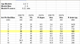
Using the table.
Go to column 5, k170 Idss.
Select the Idss value you have.
Go to column 6, j74 idss.
Select the matching Idss on the same row.
Go to column 4 R degen.
Select the matching resistor value that is added to the j74 source.
the example highlighted in yellow is k170 = 6.5mA idss, the matching Pchannel is a 7.6mA j74 with a 4r8 degeneration resistor in the j74 source.
This is what p3 does in the F5/F5t. it varies the two source resistors to give a DIFFERENCE in the FET source resistor to bring the gm of the upper and lower devices to become the same transconductance.
There is a misprint in the table, the mS unit under Idss in col5 & 6 should read mA
Attachments
Last edited:
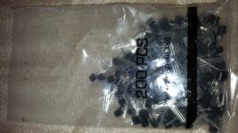
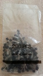
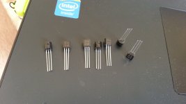
Hi.I bought 200pcs of 2sk170bl from China.Are they genuine or fake?Here is pictures with flash and not flash.Taken with Galaxy note 2
Attachments
Last edited:
I also checked the laser printing with my fingernail and it feels that printings are dented by laser
my newbie eyes say there relabeled, because original printing has a good allignment, and label colour is different. i got mine from alweit and ti-kan, both much different than yours
i also have bought 200pcs K170 BL from local store for only $20, too cheap to be true. more likely same printing as yours, but Idss check only 2-3mA
i also have bought 200pcs K170 BL from local store for only $20, too cheap to be true. more likely same printing as yours, but Idss check only 2-3mA
Last edited:
- Status
- Not open for further replies.
- Home
- Amplifiers
- Pass Labs
- 2SK170BL