Hi Bimo,
I built the ASKA clone using your layout and schematic. I'm having issues so I built a spice file but it doesn't work either. Can you take a look at it and see if you can find my error? i hope to use it to troubleshoot my boards.
Thanks, Terry
R10 value is wrong. I fix it.
Attachments
Well I learned something today. I was out of BD139 so I stuck a 2sc3423-Y in there because I had a bunch of them. Well it turns out you can't just use anything in the vbe multipliers. Every time I would try to power it up the current would go too high and light my bulb tester. I tried the 2sc3423 in the spice file and sure enough, the current would go over 250mA per device. So I pulled the c3423 and installed a MJE340 and now the bias is actually too low. Looks like it's time to order some BD139s.
Blessings, Terry
Blessings, Terry
Well I learned something today. I was out of BD139 so I stuck a 2sc3423-Y in there because I had a bunch of them. Well it turns out you can't just use anything in the vbe multipliers. Every time I would try to power it up the current would go too high and light my bulb tester. I tried the 2sc3423 in the spice file and sure enough, the current would go over 250mA per device. So I pulled the c3423 and installed a MJE340 and now the bias is actually too low. Looks like it's time to order some BD139s.
Blessings, Terry
Did you change the trimpot with fix value resistor?
No. It has a 100R pot. With the 2SC3423, 100R is not enough and with the MJE340 0R won't give me more than 4mV across one 0R33 emitter resistor.
No. It has a 100R pot. With the 2SC3423, 100R is not enough and with the MJE340 0R won't give me more than 4mV across one 0R33 emitter resistor.
I see. I must change the design to accommodate different transistor type. Maybe R6 (470 ohm) should change to 330 and R8 to 500 ohm. But I will sim it first.
Hi Bimo,
I'm not saying you should change anything, I can only report what I see. I spent two days going over every part and trace thinking I had something wrong when it turned out to be that I should have used the BD139 that your schematic called for. I suppose if you want to make it so it will work with a variety of devices in that position, you would need to lower the 470R and increase the trimmer. I will try a 200R trimmer tomorrow and see if the 2SC3423 will work.
I'm not saying you should change anything, I can only report what I see. I spent two days going over every part and trace thinking I had something wrong when it turned out to be that I should have used the BD139 that your schematic called for. I suppose if you want to make it so it will work with a variety of devices in that position, you would need to lower the 470R and increase the trimmer. I will try a 200R trimmer tomorrow and see if the 2SC3423 will work.
the Vbe multiplier "multiplies" it's own Vbe and applies that to the output. That is the bias voltage. A 2EF requires ~2.4V whereas a 3EF requires about 3.6V, A BJT driver feeding a FET SF might require 7V
If a different transistor has a different Vbe, then it will have a different output voltage.
You change the resistor ratios to get back to the output voltage that the amplifier requires.
If the resistor values are chosen such that the correct output voltage is outside the range required, then the wrong resistor values have been selected.
Last edited:
the Vbe multiplier "multiplies" it's own Vbe and applies that to the output. That is the bias voltage. A 2EF requires ~2.4V whereas a 3EF requires about 3.6V, A BJT driver feeding a FET SF might require 7V
If a different transistor has a different Vbe, then it will have a different output voltage.
You change the resistor ratios to get back to the output voltage that the amplifier requires.
If the resistor values are chosen such that the correct output voltage is outside the range required, then the wrong resistor values have been selected.
The bias servo is from Hugh Dean http://www.diyaudio.com/forums/attachments/everything-else/119278d1226042919-attention-aksa-55-hugh-thinking-let-us-see-schematics-forum-aksaconceptual.gif
You think Hugh Dean is wrong?
Several people built this schematic with BD139 transistor as bias servo. It can work.
Are you the "Designer" of your amplifier?
Then YOU as Designer has to select the resistors to give the range of output voltage that the amplifier needs.
Copying some else's values can get you started, but there is no way that another person who has no idea how you plan to use their sch and values can know what your amplifier needs.
I gave three examples of an amplifier's needs: 2.4Vdc, 3.6Vdc & 7Vdc
The amplifier Designer has to select the resistor values.
It has nothing to do with AKSA.
Last edited:
Are you the "Designer" of your amplifier?
Then YOU as Designer has to select the resistors to give the range of output voltage that the amplifier needs.
Copying some else's values can get you started, but there is no way that another person who has no idea how you plan to use their sch and values can know what your amplifier needs.
I gave three examples of an amplifier's needs: 2.4Vdc, 3.6Vdc & 7Vdc
The amplifier Designer has to select the resistor values.
It has nothing to do with AKSA.
😀
I see. Hugh Dean can not do wrong, I am nobody can do wrong.
My amplifier was built by several people. They must be wrong, too. 😀
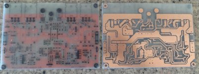
Hey guys, I didn't mean to start a fire storm. I'm sure the amp works fine with the BD139. As I said, I have run out of them. I only shared what I found because I learned something new that I thought others might benefit from. I surely never meant to suggest that there was anything wrong with this design. I plan to try a 200R trimmer with the 2SC3423 and see if that will work. Someone else may want to build this amp and would be nice to know if there are options. I can also provide a PDF for the iron transfer I used if that is OK with Bimo. I should have it playing today and I can give a report on the sound.
Blessings, Terry
Blessings, Terry
Hey guys, I didn't mean to start a fire storm. I'm sure the amp works fine with the BD139. As I said, I have run out of them. I only shared what I found because I learned something new that I thought others might benefit from. I surely never meant to suggest that there was anything wrong with this design. I plan to try a 200R trimmer with the 2SC3423 and see if that will work. Someone else may want to build this amp and would be nice to know if there are options. I can also provide a PDF for the iron transfer I used if that is OK with Bimo. I should have it playing today and I can give a report on the sound.
Blessings, Terry
It is OK, Terry. It is not your fault. 🙂
You can share the PDF.

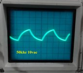
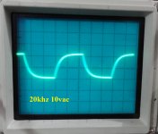
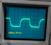
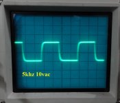
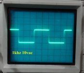
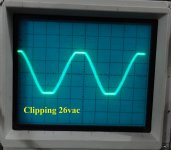
OK the saga continues. I installed a 200R in the channel that still had the 2SC3423 installed in the vbe multiplier. I adjusted the trimmer to 200R and fired it up. I'm reading 0.00 across the pair of 0.33R resistors so I start turning the adjustment screw and it seems like I have to go a long way before I start to see change but it finally does start to rise so I set it at 50mV which should be 75mA per device. Looks good so I measure the trimmer an it is 22R. What???? So for kicks and giggles I pull the MJE340 from the other channel, reinstall the 2SC3423, set the trimmer to 100R and fire it up. Bias is at 0.00 and I begin to turn the set screw and low an behold the bias rises just like it is supposed to and I set it at 50mV. I shut it down and measured the trimmer and it is 22R. So now I can't explain why on Friday Both channels had extremely high bias but today all is well. It seems 100R is just fine for the trimmer, maybe even 50R. Sorry for all the confusion. I have had it playing for about 1/2 hour and it sounds very nice. Once I've let in burn in for a while I'll compare it to some other amps. I did hook it up to the scope and it looks like it is not very fast. The square waves get pretty rounded by the time you get to 20khz. I didn't check for clipping behavior. I'll do that later. I can post some pictures of scope shots then too if anyone is interested.
Blessings, Terry
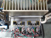
EDIT; here's a pic of it playing.
Blessings, Terry
EDIT; here's a pic of it playing.
Attachments
Last edited:
I can post some pictures of scope shots then too if anyone is interested.
Blessings, Terry
EDIT; here's a pic of it playing.
😎 Please take some pictures.
Can you compare AKSA 55 clone and Perkutut (Turledove) in A/B listening test?
Hi Bimo,
I'm attaching pics of the ASKA.
I hooked them up to the A/B system. Too close to call. Both sound lovely.
I'm attaching pics of the ASKA.
I hooked them up to the A/B system. Too close to call. Both sound lovely.
Attachments
@bimo sir good am can a ask for the parts list of a turtledove amp (bird Song) 🙂 please
You can see the schematic on my blog: https://anistardi.wordpress.com/2014/10/14/perkutut-amplifier/
C2, C10, C11 is silver mica or ceramic NP0/COG.
C1 is MKP or MKS.
You can use another type of the capacitors as you like, and the amplifier will still work 🙂
- Status
- Not open for further replies.
- Home
- Amplifiers
- Solid State
- 2SC5200 Power Amplifier