you are right about the last comment.
I don't know where to insert the Tian probe.
Do you know?
The results indicate you have asked the wrong question and as a result the model is giving a weird answer that should be investigated before you believe what you see.
May be you can use midlebrook method with less precision than tian probe. If you don't know how to measure phase margin and gain margin in ltspice, you should not comment my simulation is wrong

I made the comment
"the predicted phase margin and gain margin values are enormous."
You appear to not understand the significance.
I asked the question
"Have you asked the simulator the right questions? "
Again you appear to not understand the significance.
"the predicted phase margin and gain margin values are enormous."
You appear to not understand the significance.
I asked the question
"Have you asked the simulator the right questions? "
Again you appear to not understand the significance.
Last edited:
Hi Bimo,
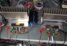
The Turtledove is singing beautifully. Very, very nice! Thanks for sharing this design with us. It played from first start up. Looks great on the scope. I have it playing right now on my A/B system. Compared it to the Honey Badger and Peeceebee so far. Holds it own very well and I just have it on a so-so PSU. 160VA 30-0-30vac transformer and 6X4700 caps. Even with this small PSU it sounds really, really good. I will be recommending this one to my friends.
Blessings, Terry
Attachments
Hi Bimo,
The Turtledove is singing beautifully. Very, very nice! Thanks for sharing this design with us. It played from first start up. Looks great on the scope. I have it playing right now on my A/B system. Compared it to the Honey Badger and Peeceebee so far. Holds it own very well and I just have it on a so-so PSU. 160VA 30-0-30vac transformer and 6X4700 caps. Even with this small PSU it sounds really, really good. I will be recommending this one to my friends.
Blessings, Terry
Thank you, if you enjoy this amplifier.
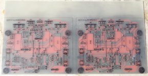
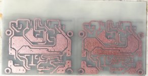
Can I put this pictures to my blog? Can you take some pictures of the scope?
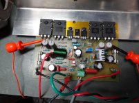
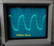
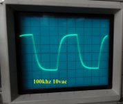
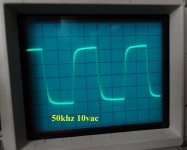
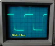
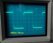
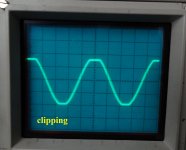
Here you go.
I used +-40V rails into an 8R dummy load. It clipped at 27Vac. Bias is set to 90ma per device.
Let me know if you need any other pictures.
Blessings, Terry
I used +-40V rails into an 8R dummy load. It clipped at 27Vac. Bias is set to 90ma per device.
Let me know if you need any other pictures.
Blessings, Terry
Attachments

Here you go.
I used +-40V rails into an 8R dummy load. It clipped at 27Vac. Bias is set to 90ma per device.
Let me know if you need any other pictures.
Blessings, Terry
😎

may be you have better method than M. Tian with tian probe?
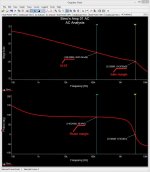
Bimo, something is not right. The graph shows the gain @ 1KHz is some 6db. Open loop. It can't be the case... too low to be truth... in this case the margins are also calculated incorrectly.
I wouldn't worry about the Micro 50S. As far as I'm concerned, I've already invested more effort than it is worth. YMMV
Bimo, something is not right. The graph shows the gain @ 1KHz is some 6db. Open loop. It can't be the case... too low to be truth... in this case the margins are also calculated incorrectly.
Of course it is right. This amplifier have low open loop gain (micron). This is the open loop gain using Bob Cordell method (insert 1GH inductor in feedback).
You make an assumption, please run the simulator 😀
Attachments
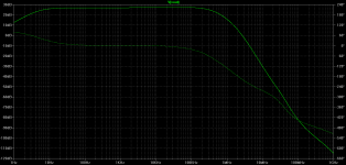
This is what I see, looking at the global loop 🙂
You're right, the loop gain is low. The margins are good, mainly because of that reason - although they are slightly lower than the ones presented earlier. But ULGF at 140 KHz shows the amp is heavily compensated (mainly with the cap between the VAS output and (-) input - influencing overall speed of the circuit and THD at the higher end of the audio frequency range, as well as phase response (around 8.5 degrees phase shift @ 20 KHz with the loop closed).
Nevertheless, it's an interesting, working low loop gain design with rather low THD (for such a low loop gain).
Cheers,
Valery
Attachments
Last edited:
This is what I see, looking at the global loop 🙂
You're right, the loop gain is low. The margins are good, mainly because of that reason - although they are slightly lower than the ones presented earlier. But ULGF at 140 KHz shows the amp is heavily compensated (mainly with the cap between the VAS output and (-) input - influencing overall speed of the circuit and THD at the higher end of the audio frequency range, as well as phase response (around 8.5 degrees phase shift @ 20 KHz with the loop closed).
Nevertheless, it's an interesting, working low loop gain design with rather low THD (for such a low loop gain).
Cheers,
Valery
This circuit is simple, class B. If it make class AB, it can achieve high ULGF, like http://anistardi.wordpress.com/2014/04/19/aksa-55-dalam-simulasi/
By the way, tian probe is easier to measure phase margin and gain margin, but I know you don't like to use Ltspice.
...
Phase Margin = 103 degree
Gain Margin = 30 dB
...
The phase margin reported from post #73 is 88.9 deg and the gain margin 24.6dB, which are different from those figures in post #49.
I tend to believe post #73 is correct, with simple Miller compensation, in theory the phase margin cannot exceed 90 degree.
The Tian probe plot in post 54 indicates an OLG of 6dB @1kHz, which is very suspicious when the CLG is much higher.
Last edited:
Hi Bimo,
I hope you don't mind but I want to try the other amp on your website.
Blessings, Terry
It is OK.
But my favorite is Blameless 150. I sell the PCB. It is mini Honey Badger (like Honey Badger but without input cascade and PSU is +-45V DC). It you want to try it, just PM your email, I will send the schematic and the gerber file. I do not want publish the schematic 😎
Do you have a write-up about that amp? I have already built a lot of Blameless amps. HB, DX Super-A, MKIII, Wolverine, etc. This ASKA clone is interesting. I'll let you know how it sounds in a couple days.
Blessings, Terry
Blessings, Terry
Do you have a write-up about that amp? I have already built a lot of Blameless amps. HB, DX Super-A, MKIII, Wolverine, etc. This ASKA clone is interesting. I'll let you know how it sounds in a couple days.
Blessings, Terry
https://anistardi.wordpress.com/2014/06/25/blameless-150/
First time I design this amp, conservatively. I was afraid to make fast amp (high slew rate). But with slew rate about 90V/uS, it better than 4 OEM amp which more expensive. But my friend said the bass is not deep. Then I tweak to get more deep bass and more fast.
The trannies that I use on Blameless 150 are not easily to find in my country 😡 Some of my friends want me to design powerful amp with "ordinary" components. The love powerful amp 😀
Hi Bimo,
I built the ASKA clone using your layout and schematic. I'm having issues so I built a spice file but it doesn't work either. Can you take a look at it and see if you can find my error? i hope to use it to troubleshoot my boards.
Thanks, Terry
I built the ASKA clone using your layout and schematic. I'm having issues so I built a spice file but it doesn't work either. Can you take a look at it and see if you can find my error? i hope to use it to troubleshoot my boards.
Thanks, Terry
Attachments
- Status
- Not open for further replies.
- Home
- Amplifiers
- Solid State
- 2SC5200 Power Amplifier