There is a little sag built into any practical power supply. At full VA rating (actual volt-amps, AC input, with a DC load) the regulation of Antek toroids is 88%. Drops to about 80% when DC output watts equals the VA rating - which is about 60% overload. You can get them tighter, but they cost. ANYBODY’s EI will be worse, it’s just the nature of the beast.
Youd have to be dreaming to get an amp from the store with 3 pair of 2N3055 per channel. Of course one could build it. Mine only ran +/-27V supply but did 100+W at 2 ohms. It was only a monoblock, built as a demo vehicle, to prove 3055‘s with 3MHz TIP drivers, didn’t have to sound as bad as the Dyna ST120.
Youd have to be dreaming to get an amp from the store with 3 pair of 2N3055 per channel. Of course one could build it. Mine only ran +/-27V supply but did 100+W at 2 ohms. It was only a monoblock, built as a demo vehicle, to prove 3055‘s with 3MHz TIP drivers, didn’t have to sound as bad as the Dyna ST120.
Attachments
Last edited:
Interesting design. I bet it sounded okay.
For sure, the Dynaco ST-120 isn't a nice amplifier. I get them for service still, Dynaco was built to be cheap. I built various Dynaco kits for people in high school. Heathkit was far superior in performance (you actually built the entire thing - and it worked!).
Still strongly prefer E-I core transformers. Music is mostly 10% or less at full power if you aren't clipping. If a few percent drop is important, either a bad design or you are in fact clipping.
You can get great sound and 75 w/ch in the dynakit ST120 chassis with an AX6 driver and a pair of 3 mhz Ft output transistors (I used NTE181, likely white box MJ15003 with same soa spec). 1/3 the parts of post 621. Same remote transistor mount of ST120, improved heat sink in my unit. Single rail regulated to 69 v. https://www.diyaudio.com/forums/solid-state/236256-retro-amp-50w-single-supply-42.html Note the 4"x4" AX6 pcb won't fit the ST120 chassis; I built point to point on 3.5"x5.5" NEMA CE laminate.
You can get the same great sound with the dynakit PC14 driver and djoffe's add-on closed circuit idle bias circuit http://www.diyaudio.com/forums/solid-state/156627-dynaco-stereo-120-can-beautiful.html but that is 7 more transistors. I cannot measure distortion but it is a lot less than the 1% HD ST70 7199 version. No audible difference at 2 watts on SP2-XT speakers to my .03% HD Peavey CS800s.
I suspect the TIP31 drivers in post 621. My AX6 had dull highs compared to the PC14-djoffe bias side of the ST120, until I changed the fairchild TIP31c/32c drivers to MJE15028/29
Per post 622, I like the stiff power supply of the EI transformer of the ST120. 75 w both channels was measured on SP2-XT (8 ohms) with only a single 3300 uf cap for both channels. There was 1000 uf pre-regulator. Dynaco PC15 regulator/current limiter was abandoned as incompatible with high gain modern transistor (limited current out to 2 amps instead of 6.5) Measurement device was 100 vac scale of a simpson 266-XLPM. There was no clipping. Volume was limited to what I could stand in my music room with earplugs.
As far as anatech's assertion that I cannot hear 1% HD, I counter do not use 1000 hz sine waves. Use a Steinway top octave track like a Peter Nero track I use off Young & Warm & Wonderful. . Or the tinkly bells of Hawaii by Denny Martin. It is necessary to have ears that still go to 14000 hz, and speakers as undistorted as the SP2-XT (at 5 watts)
Last edited:
Hi wahab,
Looking at the beta vs collector current graphs, it should be a parabola. The beta dives at higher currents. Nothing gradual about it.
Most earlier transistors showed a beta increase with current, then a decrease. Higher currents caused the beta to drop more quickly. Current parts are simply wonderful in that regard.
Hi indianajo,
1966 was a dark time for solid state. Devices weren't that good. They were all horribly expensive as you've noted. Even resistors and capacitors were pricey. To learn, we took junk apart and reused those parts. Colour TVs were treasure troves. A science fair project using three signal transistors set my dad back over $20 back then.
NTE and ECG parts were scrap and unknown parts. I know because I used to poke the leads through the bag and test them before using one, that's where I worked. They sold them and I did service for them. My return rate dropped to near zero once I stopped using that garbage and went to real parts. They were much less expensive too. Many silicon transistors even measured leaky NEW IN BAG. Total garbage. Silicon transistors should measure less than 5 uA leakage in any mode, much less in fact.
The only one thing I'll say to you is this. Any assumptions you may make on these parts is baseless. They may be the part number you suggest, but they are rejects. What that means is that they are not typical of that part number and are really something else. With Chinese companies manufacturing old part numbers, guess where they are buying now? If you expect those to be the same, you're far too optimistic.
As far as distortion is concerned, you know better than anyone that without a THD meter or audio analyzer, you don't know anything. Speakers will have far greater distortion than an amp just working as a rule. You also need to check for peaking and ringing, or out and out oscillation.
Those Solitron 2N3055’s cost next to nothing at a ham fest. So did the heat sink, from Skycraft. A few extra parts didn’t cost me any real money. It was the answer to the “Can you make a safe, decent sounding 100 watts” out of nothing but generic transistors?” The same circuit, using only EF2 and TIP32 on the PNP side sounds like ***, AS YOU WOULD EXPECT. Two miserable 14 cent TO-92’s and two 820 ohm resistors buys a near infinite step up in performance.You can get great sound and 75 w/ch in the dynakit ST120 chassis with an AX6 driver and a pair of 3 mhz Ft output transistors (I used NTE181, likely white box MJ15003 with same soa spec). 1/3 the parts of post 621. Same remote transistor mount of ST120, improved heat sink in my unit. Single rail regulated to 69 v. https://www.diyaudio.com/forums/solid-state/236256-retro-amp-50w-single-supply-42.html Note the 4"x4" AX6 pcb won't fit the ST120 chassis; I built point to point on 3.5"x5.5" NEMA CE laminate.
You can get the same great sound with the dynakit PC14 driver and djoffe's add-on closed circuit idle bias circuit http://www.diyaudio.com/forums/solid-state/156627-dynaco-stereo-120-can-beautiful.html but that is 7 more transistors. I cannot measure distortion but it is a lot less than the 1% HD ST70 7199 version. No audible difference at 2 watts on SP2-XT speakers to my .03% HD Peavey CS800s.
I suspect the TIP31 drivers in post 621. My AX6 had dull highs compared to the PC14-djoffe bias side of the ST120, until I changed the fairchild TIP31c/32c drivers to MJE15028/29
Per post 622, I like the stiff power supply of the EI transformer of the ST120. 75 w both channels was measured on SP2-XT (8 ohms) with only a single 3300 uf cap for both channels. There was 1000 uf pre-regulator. Dynaco PC15 regulator/current limiter was abandoned as incompatible with high gain modern transistor (limited current out to 2 amps instead of 6.5) Measurement device was 100 vac scale of a simpson 266-XLPM. There was no clipping. Volume was limited to what I could stand in my music room with earplugs.
As far as anatech's assertion that I cannot hear 1% HD, I counter do not use 1000 hz sine waves. Use a Steinway top octave track like a Peter Nero track I use off Young & Warm & Wonderful. . Or the tinkly bells of Hawaii by Denny Martin. It is necessary to have ears that still go to 14000 hz, and speakers as undistorted as the SP2-XT (at 5 watts)
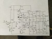
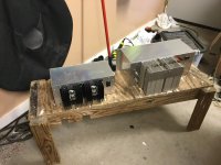
The amp that replaced this on my test bench runs off a 68 volt single rail and 2 channel. EF3 output that doesn’t even use complementary - a single 2N5303 paired with a 2N6030. “Proper” sustained beta drivers and predrivers, singleton input, and darlington VAS. You’d never suspect from the sound of it that it was just made with “whatever was lying around”, and that it has a dreaded output capacitor. I’ve run the hell out of it on 2 ohms (per channel) too. The one on the right is something I call the “AC300A”. Adds an op amp front end (with nested feedback) goes to 120V rail, and uses 4 pair of 2N3773/MJ15004, and has absolute short circuit protection. Kind of remind you of anything?
Attachments

Hi wahab,
Looking at the beta vs collector current graphs, it should be a parabola. The beta dives at higher currents. Nothing gradual about it.
Most earlier transistors showed a beta increase with current, then a decrease. Higher currents caused the beta to drop more quickly. Current parts are simply wonderful in that regard.
Hi Anatech, i posted a few operating points, we can see that the gain is around 110 --> 90 up to 1A and start to fall abruptly above 1.5A, that s exactly what is displayed in the datasheet.
110/120mA, 93/840mA, 75/1.5A, 41/3.6A, and so on to 31/5.2A
Indeed and always liked the triple for Quasi but was little hard to tame for stability.
Without the differential input, could be much easier to make a stable amplifier.
Feedback loop after output cap should improve bass , be able to use shown smaller cap.
I could see potential to get to much lower distortion with fine tune.
And just keep it single supply for fun
Although i appreciate triples i ve always been suspicious of QC and compound OSs, IIRC i built only one amplifier of this kind using a pair of 2N3055 and i soon replaced them with a BDW51C/52C complementary pair, on the other hand i was and still is very fond of darlingtons for the simplicity they provide not couting that they are much more rugged than one could think, whenever i stumbled on a QC to service, when it was a guitar amp, i replaced the QC by a pair of complementary darlingtons and so far there wasnt a single return.
Hi wahab,
Yes, you did post those points. I remember clearly from Motorola data sheet graphs of that era, those parts were pretty bad. I can always look them up again since I have those old data books still, but the time isn't worth it. My own experience with them agreed with published data. This is for devices purchased new at the time, and some surplus parts (new but older).
I also have (somewhere) the datasheets from Lambda where fT was 19 KHz on those. That's so they wouldn't oscillate mounted on remote heat sink as was common practice at the time.
Unless a Darlington transistor has a built-in "speedup" resistor from base to emitter inside on the second transistor, they are slow parts. They work, but you are better off with discrete parts. New Darlington transistors for audio always have these resistors built in.
Hi wahab,
Yes, you did post those points. I remember clearly from Motorola data sheet graphs of that era, those parts were pretty bad. I can always look them up again since I have those old data books still, but the time isn't worth it. My own experience with them agreed with published data. This is for devices purchased new at the time, and some surplus parts (new but older).
I also have (somewhere) the datasheets from Lambda where fT was 19 KHz on those. That's so they wouldn't oscillate mounted on remote heat sink as was common practice at the time.
Unless a Darlington transistor has a built-in "speedup" resistor from base to emitter inside on the second transistor, they are slow parts. They work, but you are better off with discrete parts. New Darlington transistors for audio always have these resistors built in.
I ll re do a test for the fun with some Motorola models that i ve still at hand, from memory the gain is about 80 at 1A,
with a MJ2955 you could do a very good amp with just an EF2 provided that it had no more than 3A current, indeed
in simulations with an EF2 there s a brutal increasement of H3 past this value and it is ubiquitous for all such epitaxial
devices that were generic of the 2N3055, including the old darlintons like MJ2500-2501/3000-3001, TIP141-142/146-147, BDV64/65-BDX66/67 that were all generic of this transistor.
All those old power darlingtons have a resistance that goes from the emitter of the driver to the emitter of the power transistor,
typicaly 60-120R depending of the device, the higher the TDP the lower the resistance, it is 70R in some high quality Sanken darlingtons, these ones have tremendous gain and Ft contrary to the old epitaxial from the late 70s.
3 amps of current is only a 28 volt rail and 8 ohm load only. So three in parallel is about right if you want to drive a low impedance load. For “8 ohm only use” you can get by with a damn TO-220. They’ll just blow at 4 ohms, but if you never abuse it they’ll run forever.
Those Sanken darlingtons are nice. The best ones handle full power to like 70 volts, and give me less stability problems than the old school ones. The problem with the old school ones is the driver is no better than a TIP31 speed wise. And the monolithic ones don’t really like being run in triples because the base-emitter resistor for the driver is in the wrong place. They simply omit it on the Sankens, leaving only the one on the output. They run fine in triples with a TO-92 predriver, and a resistor hung from base to output rail. And have enough gain where you don’t really need to unless you WANT to (ie, lowering Zout when clipping - a little habit I picked up from the rave DJ days).
Those Sanken darlingtons are nice. The best ones handle full power to like 70 volts, and give me less stability problems than the old school ones. The problem with the old school ones is the driver is no better than a TIP31 speed wise. And the monolithic ones don’t really like being run in triples because the base-emitter resistor for the driver is in the wrong place. They simply omit it on the Sankens, leaving only the one on the output. They run fine in triples with a TO-92 predriver, and a resistor hung from base to output rail. And have enough gain where you don’t really need to unless you WANT to (ie, lowering Zout when clipping - a little habit I picked up from the rave DJ days).
Last edited:
No, kind of a “DC300A” with output and input caps. it’s short circuit current is limited to just over 8.5 amps. But will drive a typical 2 ohm load (4 pairs of speakers in parallel). The idea is not to spot weld. And enough heat sink where it can actually do it for more than 15 seconds at a time (unlike the original).Hi wg_ski,
Spot welder? lol!
I thought about doing a 2N3055/MJ2955 version with stacked series outputs. But it would take 16 per channel, and that’s a LOT of drilling and I doubt I could fit it in that form factor. I started a PCB design with a “tunnel” heat sink, and two boards would clam shell together, but like many projects remains unfinished. The board design is around here somewhere in one of the many 2N3055 threads.
You know, I've rebuilt enough DC300A amplifiers. They used an excellent op amp. Still, didn't sound very good.
Stacked outputs. Not a great idea, like a Marantz 510 amplifier and many others. They can have stability issues too. ... And yeah! WAY too much drilling and mounting, but you would have all kinds of heat spreading.
Tunnel heat sinks work great, but need the fan to run all the time at low speed at least. Great examples would be the Marantz 500, 2500, 2600 and 510, Luxman M05, I think the Yamaha EMX-300 used a one sided tunnel and very effectively made a flat, powered mixer. I may have the model # wrong. Paging amplifiers once used a bit of sheet metal against a finned heat sink to form a tunnel, again more effective cooling (Yamaha turned this on it's side). I'm sure there are many other very good examples as well as junk that used a form of a tunnel.
The worst thing about a tunnel is the fan noise. Then as the fan ages it picks up dust and other deposits and that gets noisy. The bearings eventually become noisy as well. I like convection cooling, no fan to fail or plug up. If it has an air filter, almost no one cleans or replaces them. The best part is that they are quiet and don't pretend to be vacuum cleaners.
A true high power class A/B gem available at a ridiculous price!
This is my low THD, M-1400 amp. 🙂
https://www.electronicmusic.com/features/reviews/hardware/m1400.html
This is my low THD, M-1400 amp. 🙂
https://www.electronicmusic.com/features/reviews/hardware/m1400.html
PS.
For domestic use, I made a simple fan speed modification to reduce low speed without affecting (hot) high speed.
( self powered using just one zener diode, one resistor and one small relay )
For domestic use, I made a simple fan speed modification to reduce low speed without affecting (hot) high speed.
( self powered using just one zener diode, one resistor and one small relay )
Did you mean ±70 Vdc? Never would have MJ2955's/2N3055's coped with supply voltages as high as this. Paralleling multiple devices also would not have helped either.I preferred the Motorola version of 2n3055 along with their MJ2955 used in amps with 70V rails. 3 pairs of them would do 200W rms into 4 ohms all day with the right heat sink...
Anyway, about 50 years ago we could have mail ordered a 200 watt amplifier kit from a German dealer. The design featured two pairs of these devices, all in series! I never put an order, though...
Best regards!
No, that would be a single 70V rail, which was done all the time. But probably not 200 RMS at 4, closer to 100. 3 pairs of outputs would at least get the peak output currents down in the 3-5 amp range.
Series connecting a single pair? Not on your life. There isn’t enough beta at 15 amps to be useful at all. Almost any other epi-base type will do better. Amps that successfully did that used the 20 and 30 amp parts. And still you want to parallel. As I stated earlier “that’s a lot of drilling!”. Even if the transistors themselves were effectively free. Up until about 5 years ago, I was on the “hunt” for all manner of vintage TO-3’s. Even the 60 to 80 volters. Bought up a lot of surplus at a buck or two each and now have a hell of a stash. Allows me to play around with old designs for next to nothing, and when vintage equipment (from the 2N3055 era) comes in for repair I’ve got what I need without resorting to using up MJ15024’s. Which are now getting valuable.
And every batch checked for fakes. Always sacrifice one or two.
Not a single pair, but two pairs. Two 2N3055's in series beneath the positive rail, two MJ2955's in series at the negative one. I have teh schematics and build instructions (in German...) as a PDF document, but I think it isn't possible to upload it here.
Best regards!
Best regards!
Guess that it was musical rather than RMS power and of course with a 4R impedance, that was an habit at the time for german brands like Dual, Grundig and other Telefunken since this helped pumping up the numbers, often they didnt even bother to specify the power on a 8R impedance.Anyway, about 50 years ago we could have mail ordered a 200 watt amplifier kit from a German dealer. The design featured two pairs of these devices, all in series! I never put an order, though...
- Home
- Amplifiers
- Solid State
- 2N3055 inside - commercial famous amplifier models, quasi complementary power output